Эта версия возможно содержит некорректные исправления. Переключить на последнюю проверенную версию.
Выберете то, что вам нужно
-
Этот шаг не переведен. Помогите перевести
-
Remove the ten 8.9mm Tri-wing Y1 screws hidden underneath square stickers.
-
Lift up the back plate.
-
-
Этот шаг не переведен. Помогите перевести
-
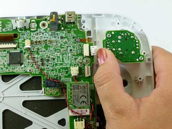
Unplug the connector that connects the back plate to the motherboard.
-
Remove the back plate.
-
-
Этот шаг не переведен. Помогите перевести
-
Take out the left and right shoulder buttons in the upper corners.
-
Remove the ZR and ZL trigger buttons by lifting up and sliding outward.
-
-
-
Этот шаг не переведен. Помогите перевести
-
Remove the top rubber cover by pulling it off of its mounts to access one of the mounting screws.
-
Remove the four 5.2mm Phillips #0 screws.
-
-
Этот шаг не переведен. Помогите перевести
-
Use a spudger to lift the tab which releases the blue ribbon cable.
-
Remove the analog stick and button cover.
-
-
Этот шаг не переведен. Помогите перевести
-
Use your thumb and push the connector towards the rightmost edge to disconnect the analog stick cable connector.
-
-
Этот шаг не переведен. Помогите перевести
-
Remove the two 9.0mm Tri-wing Y0 screws.
-
Lift out the analog stick.
-
-
Этот шаг не переведен. Помогите перевести
-
Lift up and remove the rubber cover for the directional pad.
-
Remove the directional pad buttons.
-


Отменить: Я не выполнил это руководство.
11 участников успешно повторили данное руководство.

Команда

Cal Poly, Team 17-20, Forte Winter 2013 Участник Cal Poly, Team 17-20, Forte Winter 2013
CPSU-FORTE-W13S17G20
5 членов
Автор 38 руководств