Эта версия возможно содержит некорректные исправления. Переключить на последнюю проверенную версию.
Выберете то, что вам нужно
-
Этот шаг не переведен. Помогите перевести
-
Remove five baseplate screws using a Phillips #00 screwdriver.
-
-
Этот шаг не переведен. Помогите перевести
-
Press and slide the battery cover retainer clip to the left. Use tweezers to lift the battery cover away.
-
-
Этот шаг не переведен. Помогите перевести
-
Remove the single screw from the battery housing using a Phillips #00 screwdriver.
-
-
Этот шаг не переведен. Помогите перевести
-
Using tweezers, lift the rubber plate to expose the ports.
-
-
Этот шаг не переведен. Помогите перевести
-
Remove two screws from the ports using a Phillips #00 screwdriver.
-
-
Этот шаг не переведен. Помогите перевести
-
Use a spudger to pry the faceplate away from the rest of the camera.
-
-
-
Этот шаг не переведен. Помогите перевести
-
To avoid disconnection of the connector line to the motherboard, use caution when pulling faceplate away from camera case.
-
-
Этот шаг не переведен. Помогите перевести
-
Using a Phillips #00 screwdriver, remove three screws fastened to the camera backplate edge.
-
-
Этот шаг не переведен. Помогите перевести
-
Using a Phillips #00 screwdriver, remove the two camera flash screws secured to either side of bulb housing component.
-
-
Этот шаг не переведен. Помогите перевести
-
Using an iFixit opening tool, pry the backplate from the camera internal housing component.
-
-
Этот шаг не переведен. Помогите перевести
-
Pull the backplate away from the camera internal housing component.
-
-
Этот шаг не переведен. Помогите перевести
-
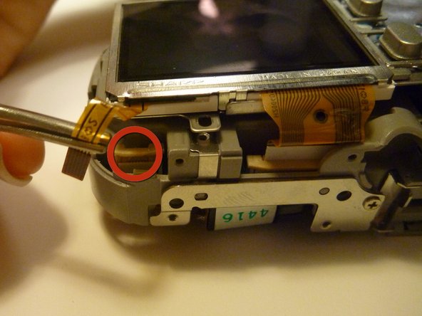
Remove one screw Phillips #00 from the right side of the LCD screen camera internal housing component.
-
-
Этот шаг не переведен. Помогите перевести
-
To check that all screws are removed from the exterior side panel, gradually slide and lift no more than 3cm away from the camera internal component body.
-
-
Этот шаг не переведен. Помогите перевести
-
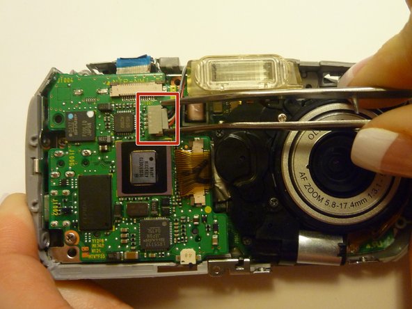
View the front of the camera internal housing component.
-
Using tweezers, detach the gray connector and blue wiring tape.
-
-
Этот шаг не переведен. Помогите перевести
-
View the top of the camera internal housing component.
-
Using tweezers, gently lift the black tape exposing all connector wires.
-
-
Этот шаг не переведен. Помогите перевести
-
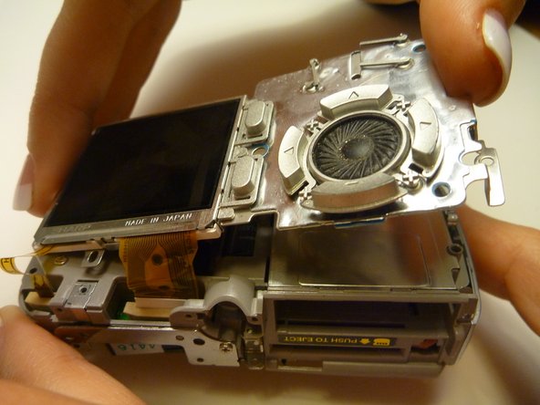
View the bottom of the camera internal housing component.
-
Use tweezers to gently wiggle, pull, and detach tape from the surface of the camera internal housing component.
-
-
Этот шаг не переведен. Помогите перевести
-
View the front of the camera internal housing component.
-
Using tweezers, gently lift the speaker, cautiously maneuvering the wire away from the side of the internal housing component toward the front of the camera internal housing component.
-
-
Этот шаг не переведен. Помогите перевести
-
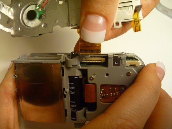
Gently lift the LCD screen away from the camera internal housing component hinging the thick yellow wiring tape attached to the camera internal housing component.
-
Use a forefinger and thumb to gently pull the thick yellow wiring tape out of the camera internal housing component.
-


Команда

Cal Poly, Team 28-23, Regan Spring 2010 Участник Cal Poly, Team 28-23, Regan Spring 2010
CPSU-REGAN-S10S28G23
4 членов
Автор 14 руководств