Эта версия возможно содержит некорректные исправления. Переключить на последнюю проверенную версию.
Выберете то, что вам нужно
-
Этот шаг не переведен. Помогите перевести
-
Remove gimbal from base handle by loosening round plate found at the top of the handle.
-
-
Этот шаг не переведен. Помогите перевести
-
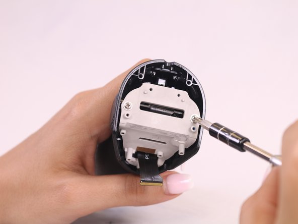
Use Phillips #00 screwdriver to remove the three screws found on the gimbal stabilizer to detach handle from gimbal.
-
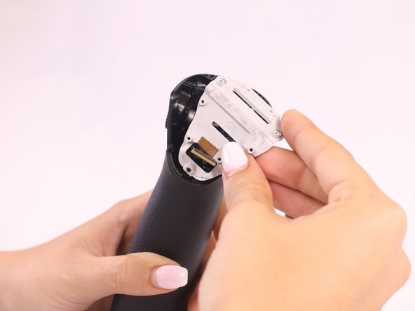
Carefully detach handle from gimbal and disconnect the cable that connects the two.
-
-
Этот шаг не переведен. Помогите перевести
-
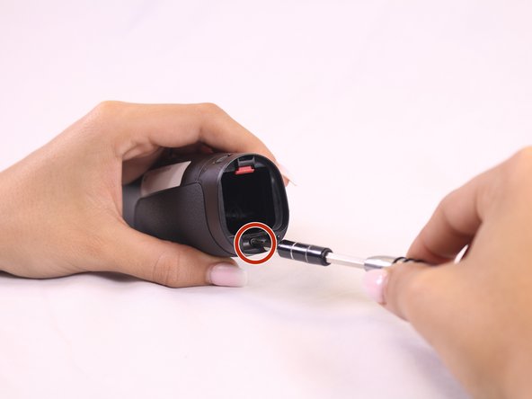
Locate the hex screws found at the top base of the handle, and unscrew using the 1.5mm hex screwdriver.
-
-
-
Этот шаг не переведен. Помогите перевести
-
Remove the quick release PCBA by locating the connecting wires and release the ribbon cable with tweezers.
-
Use the spudger to pry open and remove the face plate, starting at the back of the handle.
-
-
Этот шаг не переведен. Помогите перевести
-
Locate four screws directly on top of handle.
-
Unscrew the silver, bottom two screws, that are closest to the face plate using the 00 screwdriver.
-
Unscrew the black, top two screws, located furthest from the face plate, using the 0 screwdriver.
-
Remove the remaining two screws found on the front of the faceplate.
-
Remove the rest of the face plate shell.
-
-
Этот шаг не переведен. Помогите перевести
-
Locate and remove the black screw found at the base of the grey mounting plate.
-
Remove the grey face plate.
-
-
Этот шаг не переведен. Помогите перевести
-
Open the battery hatch and remove it by using the tweezers to press the hinge into the device.
-
Remove the black screw located underneath where the battery hatch was.
-
-
Этот шаг не переведен. Помогите перевести
-
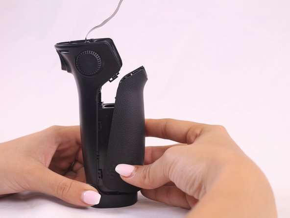
Use the spudger to remove the front handle casing by sliding the spudger into the area between the handle grooves.
-
Slide the spudger around the groove to find the 6 clasps that hold the front part of the handle, and unclasp them.
-
Take off the front handle section to reveal the whole interior of the device.
-
-
Этот шаг не переведен. Помогите перевести
-
Locate and remove the black screw in the center of the motherboard chip.
-
Remove motherboard and replace.
-


Команда

USF Tampa, Team S2-G1, Nance Fall 2017 Участник USF Tampa, Team S2-G1, Nance Fall 2017
USFT-NANCE-F17S2G1
4 членов
Автор 12 руководств