Эта версия возможно содержит некорректные исправления. Переключить на последнюю проверенную версию.
Выберете то, что вам нужно
-
Этот шаг не переведен. Помогите перевести
-
Place the 3DS upside down. Remove the game card, headphones, charging cable, stylus, or anything else that may be connected to the device.
-
-
Этот шаг не переведен. Помогите перевести
-
Using a JIS #0 screwdriver, loosen the two black screws on the back.
-
-
Этот шаг не переведен. Помогите перевести
-
The battery is located on the left hand side of the 3DS - to remove, use the small gap located at the top-middle and pull up with a non metal pointed tool.
-
-
Этот шаг не переведен. Помогите перевести
-
Using a JIS #000 screwdriver, remove the six 6mm screws around the edges of the secondary cover.
-
-
Этот шаг не переведен. Помогите перевести
-
Using tweezers, carefully pop out the rubber bumpers located at the top side of the 3DS. Removing them will reveal another two 6mm screws. Remove these screws using a JIS #000 as well.
-
-
Этот шаг не переведен. Помогите перевести
-
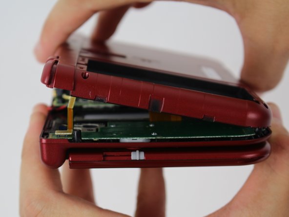
To separate the cover, carefully lift it up and away from the hinges (in order to clear the headphone port), then pivot it towards the hinges to expose the circuit boards.
-
-
-
Этот шаг не переведен. Помогите перевести
-
Use a pair of tweezers to lift away the two plugs that latch the L/R/ZL/ZR button ribbons to the motherboard. You can now remove the back cover completely and set it aside.
-
-
Этот шаг не переведен. Помогите перевести
-
Use tweezers to flip up the small, hinged locking flap in order to unlock the ZIF connector securing the circle pad ribbon.
-
Slide the ribbon out of the ZIF connector.
-
-
Этот шаг не переведен. Помогите перевести
-
Using a JIS #000 screwdriver, remove the two 8 mm screws securing the circle pad.
-
-
Этот шаг не переведен. Помогите перевести
-
Lift the circle pad casing upward to remove it. There will be some friction, but it should not require excessive force.
-
-
Этот шаг не переведен. Помогите перевести
-
Locate the gold terminal plug with a red cable at the top left of the motherboard. Using your fingers, carefully pull the plug straight upward to remove.
-
Use a pair of tweezers to disconnect the single ribbon connector.
-
-
Этот шаг не переведен. Помогите перевести
-
Using tweezers, gently pull the five marked ribbons out of the ZIF connectors along the sides of the motherboard.
-
Three of the ribbon connectors have plastic clamping flaps that cover the ribbon to prevent slippage. Use the tweezers to flip them up before ribbon removal.
-
-
Этот шаг не переведен. Помогите перевести
-
Using a JIS #000 screwdriver, remove six 4mm screws along the edges of the motherboard.
-
-
Этот шаг не переведен. Помогите перевести
-
Carefully pivot the motherboard 90 degrees toward the hinges to reveal two more ZIF connectors on the underside of the motherboard.
-
Both have latches that must be flipped up. The left, longer latch is black; the right, shorter one is white. Flip up the flaps, slide the ribbons out and remove the motherboard.
-
-
Этот шаг не переведен. Помогите перевести
-
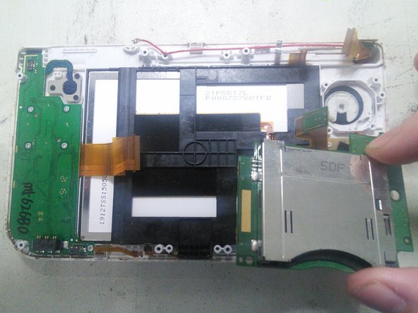
A l'aide d'un tournevis JIS #000 enlevez les 3 vis
-
Retirez ensuite le lecteur de cartouche en le soulevant.
-
-
Этот шаг не переведен. Помогите перевести
-
La pièce marquée en rouge est le support de l'antenne NFC, il faut l'enlever avant d'accéder au bloc LCD/Tactile.
-
Dégagez les clips du support plastique de l'antenne NFC à l'aide d'un outil fin sur le haut et le bas puis détachez-le.
-
-
Этот шаг не переведен. Помогите перевести
-
Glissez un outil plat entre le support noir du LCD/Tactile et le boitier de la console puis soulevez-le doucement. Glissez ensuite un médiator en dessous pour le maintenir.
-
Ensuite, vous pouvez soit soulever l'ensemble en le poussant par dessous, soit continuer à faire le tour pour déclipser l'ensemble et l'extraire.
-
-
Этот шаг не переведен. Помогите перевести
-
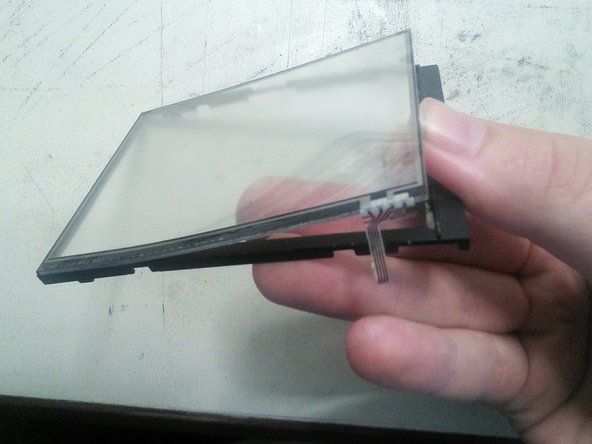
Glissez un outil fin entre le LCD et le boitier noir de l'ensemble puis soulevez doucement. Le LCD devrait sortir sans forcer.
-
-
Этот шаг не переведен. Помогите перевести
-
Chauffez les contours du tactile pour le décoller plus facilement puis poussez le doucement par dessous avec vos doigts pour l'extraire.
-


Отменить: Я не выполнил это руководство.
16 участников успешно повторили данное руководство.

Команда

12 Комментариев
I followed this guide to the letter last night on my hyrule gold new 3ds XL (from hence forth I will refer to this unit as my “old n3dsXL”) before attempting the same repair on my new unit. It worked fine on my old n3dsXL. So I went ahead with doing the same repair on my new unit.
Well it went fine till I tried to turn it on. The blue light comes on then after a few seconds there’s a “pop” sound and the unit turns back off. Can anyone tell me what just happened here?
Also tried putting the original touch screen back in the new unit and it still does the same pop sound and shuts off
You might need to reseat the cables i had this issue on my old ds lite and my old n3ds all i had to do was that and it fixed it for me also if that doesn’t work get a cotton swab and dip it in rubbing alcohol and clean the end of the ribbon cables then re insert them.
Same thing happened to me my first time—brief blue light but would not power on. Tore it down and re-connected all the cables more carefully the second time. That fixed it.
BBW -
I just disassembled my new 3ds xl to clean my lower screen and touch sensor following this guide, it went smoothly but now everything works except the touch sensor, why??
I have done this successfully three times now—thank you for the excellent guide. Newcomers should know there is one ERROR and one OMISSION in the procedure. (1) ERROR - In Step 13, the topmost ZIF connector marked in red *does* have a clamp, unlike the other four. If you attempt to pull the connector loose without opening the clamp you will break it—see the frustrated comments to Step 13 for examples. (2) OMISSION - At Step 16, before removing the cartridge drive you must unplug the connector at the top of the component. This is shown as unplugged in the photo, but the step is missing from the written instructions. The clamp on this plug loosens on the *opposite* side from where the cable is inserted, unlike the other clamps in the guide.