Эта версия возможно содержит некорректные исправления. Переключить на последнюю проверенную версию.
Выберете то, что вам нужно
Видео обзор
-
Этот шаг не переведен. Помогите перевести
-
Pry with a plastic opening tool, or your fingernail, in the divot to the left of the rear-facing camera, near the power button.
-
-
Этот шаг не переведен. Помогите перевести
-
Lift the rear case by the corner nearest the divot and remove it from the phone.
-
-
Этот шаг не переведен. Помогите перевести
-
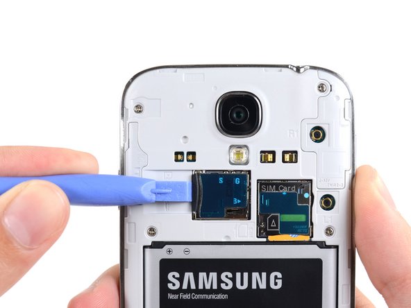
Use the flat end of a spudger, or your fingernail, to press the microSD card slightly deeper into its slot until you hear a click.
-
After the click, release the card and it will pop out of its slot.
-
Remove the microSD card.
-
-
Этот шаг не переведен. Помогите перевести
-
Insert a plastic opening tool, or your finger, into the notch of the battery compartment and lift the battery upward.
-
Remove the battery from your phone.
-
-
Этот шаг не переведен. Помогите перевести
-
Use a plastic opening tool, or your fingernail, to press the SIM card slightly deeper into its slot until you hear a click.
-
After the click, release the card and it will pop out of its slot.
-
Remove the SIM card.
-
-
Этот шаг не переведен. Помогите перевести
-
Remove the nine 4.0 mm Phillips #00 screws securing the midframe to the display assembly.
-
-
Этот шаг не переведен. Помогите перевести
-
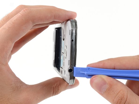
Starting on the volume button side of the phone, insert your plastic opening tool between the chrome bezel around the display glass and the larger chrome border piece. Look for the seam between the two.
-
Slide the opening tool along the seam, separating the plastic clips as you go.
-
-
Этот шаг не переведен. Помогите перевести
-
Continue prying around the corner of the phone.
-
Slide your opening tool along the seam between the midframe and display along the bottom of the device, releasing more of the plastic clips.
-
-
Этот шаг не переведен. Помогите перевести
-
Again, pry around the corner, to the power button side.
-
Slide the opening tool along the seam.
-
-
Этот шаг не переведен. Помогите перевести
-
Continue sliding the opening tool around the top of the phone, releasing the last of the clips and freeing the midframe from the display assembly.
-
-
-
Этот шаг не переведен. Помогите перевести
-
Use the flat end of a spudger to disconnect the USB board connector.
-
Disconnect the front-facing camera cable connector.
-
Disconnect the earpiece speaker assembly cable connector.
-
-
Этот шаг не переведен. Помогите перевести
-
Disconnect the headphone jack assembly cable connector.
-
Disconnect the display/digitizer cable connector.
-
Disconnect the antenna cable connector.
-
-
Этот шаг не переведен. Помогите перевести
-
Remove the single 2.4 mm Phillips #00 screw from the motherboard assembly.
-
-
Этот шаг не переведен. Помогите перевести
-
Remove the single 2.4 mm Phillips #00 screw securing the headphone jack assembly to the display assembly.
-
-
Этот шаг не переведен. Помогите перевести
-
If present, remove the 2.4 mm PH #00 screw securing the upper display assembly bracket.
-
Remove the upper display assembly bracket from the display.
-
-
Этот шаг не переведен. Помогите перевести
-
Remove the earpiece speaker assembly from the display assembly.
-
-
Этот шаг не переведен. Помогите перевести
-
Insert the tip of a spudger under the vibrator to free it from the adhesive holding it to the display assembly.
-
Use the tip of a spudger to pry the vibrator cable up from the display assembly.
-
-
Этот шаг не переведен. Помогите перевести
-
Remove the vibrator from the rear of the display assembly.
-
-
Этот шаг не переведен. Помогите перевести
-
Gently insert the point of a spudger between the USB port and the USB port bracket to pry one side of the bracket off of its post.
-
-
Этот шаг не переведен. Помогите перевести
-
Disconnect the soft button cable from the USB board cable. Be extra careful here, once you have removed the cable, carefully peel it away from the USB board
-
Disconnect the antenna connector cable from the USB board.
-
-
Этот шаг не переведен. Помогите перевести
-
Gently insert the flat end of a spudger beneath the USB board to free it from the adhesive holding it in place.
-
-
Этот шаг не переведен. Помогите перевести
-
Peel up and remove the antenna connector cable from its channel in the rear of the display assembly.
-


Отменить: Я не выполнил это руководство.
597 участников успешно повторили данное руководство.


28 Комментариев
HELP! step 28 just ends how do I insert the new one, how do I resemble the parts that used adhesives to stick?
Nearly all the guides end like this, you just need to work backwards through the steps using the new hardware.
Just work backwards like Nick stated. I usually reverse assemble the parts I take off so I know the order in which I need to put them back in.
Just run it along its track. Use a plastic spudger to push it down. Use 3m double sided adhesive tape to re-attach parts that require adhesive.