Эта версия возможно содержит некорректные исправления. Переключить на последнюю проверенную версию.
Выберете то, что вам нужно
-
Этот шаг не переведен. Помогите перевести
-
Use the iFixit Opening Tool to pry off the back case, moving the tool around the screen.
-
-
Этот шаг не переведен. Помогите перевести
-
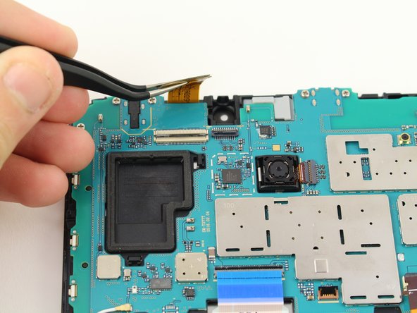
Use the tweezers to lift the switch connecting the back camera to the motherboard.
-
Use your hand to remove the back camera from the motherboard.
-
-
Этот шаг не переведен. Помогите перевести
-
Use the tweezers to lift the switch connecting the front camera to the motherboard.
-
Remove the front camera from the motherboard by lifting with the tweezers.
-
-
Этот шаг не переведен. Помогите перевести
-
Use the tweezers to flip the switch on the bottom of the strap that goes over the battery.
-
Release the strap from the switch by lifting the strap with your hand.
-
-
-
Этот шаг не переведен. Помогите перевести
-
Use the tweezers to flip the switch that connects the top of the strap to the motherboard.
-
Lift the top end of the strap with your hand and remove the strap completely from the device.
-
-
Этот шаг не переведен. Помогите перевести
-
Use the tweezers to flip the switch of the connector.
-
Lift the connector from the motherboard.
-
-
Этот шаг не переведен. Помогите перевести
-
Use the tweezers to flip the switch of the blue connector on the motherboard.
-
Lift the connector from the motherboard.
-
-
Этот шаг не переведен. Помогите перевести
-
Use the tweezers to flip the switch of the connector that runs from the battery to the motherboard.
-
Lift the connector from the motherboard.
-
-
Этот шаг не переведен. Помогите перевести
-
Use a JIS #00 screwdriver to remove the six 4.5mm screws at the top of the motherboard.
-
Lift the motherboard with your hand to detach the motherboard from the device.
-


Отменить: Я не выполнил это руководство.
6 участников успешно повторили данное руководство.

Команда

Cal Poly, Team S13-G4, White Fall 2018 Участник Cal Poly, Team S13-G4, White Fall 2018
CPSU-WHITE-F18S13G4
4 членов
Автор 8 руководств
4 Комментариев
My tablet fell into a sink full of water. I may eventually have to replace the charging port. I appreciate your instructions. I think I can do it. I haven’t shopped yet for one. May I ask where one may find a replacement for the charging port? Also, is that the only part I would need? I am getting the message (approx. I can’t remember completely) “battery temperature too low, charging will take place when temperature…”. Thank you for any reply.
It’s definitely not this simple. You’ll need a precision hot air gun, flux, solder braid to help remove the old solder from the anchor holes, heat protection tape, solder, and a soldering iron. You’ll need to use the hot air gun with tape down to protect nearby components to remove the old port. Then use flux and braid to remove solder from the 4 holes. You’ll need to flux and apply new solder evenly and put then new port on. Make sure it is completely flat and then solder the anchors using a solder gun. Use the hot air gun again until all connections are good. Clean off the flux with some alcohol.
Do you know the part number/ the name of the part so I can order it for my tablet?