Эта версия возможно содержит некорректные исправления. Переключить на последнюю проверенную версию.
Выберете то, что вам нужно
-
Этот шаг не переведен. Помогите перевести
-
Place the laptop upside-down with the display hinges facing away from you.
-
-
Этот шаг не переведен. Помогите перевести
-
Slide the latch for the right battery bay to the right and hold.
-
Continue to hold the latch while using a plastic opening tool to lift and remove the battery bay cover.
-
Remove the battery.
-
-
Этот шаг не переведен. Помогите перевести
-
Loosen the two captive screws on the bottom left corner of the hard drive using a Phillips #1 screwdriver until you hear a click.
-
-
Этот шаг не переведен. Помогите перевести
-
Lift the hard drive cover using a non-marring iFixit opening tool.
-
-
Этот шаг не переведен. Помогите перевести
-
Slide the hard drive to the left using your fingers.
-
Remove the hard drive by inserting an iFixit opening tool under the right side of the hard drive and carefully lifting it out.
-
-
Этот шаг не переведен. Помогите перевести
-
Using a Phillips #1 screwdriver, turn the screw on the RAM cover until you hear a click.
-
-
Этот шаг не переведен. Помогите перевести
-
Remove the RAM cover by inserting the plastic opening tool into the indent and lifting.
-
-
Этот шаг не переведен. Помогите перевести
-
Push the white and silver retaining clips away from each side of the RAM card using your fingernails.
-
-
Этот шаг не переведен. Помогите перевести
-
Pull the RAM card away from the computer.
-
Repeat Steps 6 and 7 to remove the other RAM card that may be installed.
-
-
-
Этот шаг не переведен. Помогите перевести
-
Remove the strip of plastic at the right furthermost edge of the keyboard using a plastic opening tool.
-
Insert the plastic opening tool at either end of the strip.
-
Lift upwards and proceed to the other end while repeating this lifting process every one to two inches.
-
-
Этот шаг не переведен. Помогите перевести
-
Remove the two 3-mm screws at the top edge of the keyboard using a Phillips #00 screwdriver.
-
-
Этот шаг не переведен. Помогите перевести
-
Pry the top of the keyboard loose from its casing using a plastic opening tool.
-
-
Этот шаг не переведен. Помогите перевести
-
Gently grasp the top of the keyboard and pull it up and toward the screen.
-
-
Этот шаг не переведен. Помогите перевести
-
Gently push the two tabs locking the black ribbon cable.
-
To remove the black ribbon cable from the motherboard, slide the keyboard toward the screen.
-
You may now safely separate the keyboard from the laptop.
-
-
Этот шаг не переведен. Помогите перевести
-
Place the laptop upside-down with the display hinges facing away from you.
-
-
Этот шаг не переведен. Помогите перевести
-
For the following steps, use a Phillips #1 screwdriver.
-
Remove the twelve 6-mm screws that border the bottom of the laptop.
-
Remove the 6-mm screw located in the lower middle of the device.
-
Remove the three 3-mm screws located in the battery bay.
-
Remove the one 4-mm screw located near the RAM.
-
-
Этот шаг не переведен. Помогите перевести
-
Use a Phillips #1 screwdriver to remove the five 6-mm screws in the keyboard slot.
-
-
Этот шаг не переведен. Помогите перевести
-
Lock the white ribbon cable into place by gently pulling on the two black tabs.
-
Remove the white ribbon cable by pulling it towards you.
-
Remove the connector that has the blue, red, black, and white wires using tweezers.
-
-
Этот шаг не переведен. Помогите перевести
-
Separate the laptop upper casing from the lower casing by using an opening tool around the sides of the case to pry it apart.
-
-
Этот шаг не переведен. Помогите перевести
-
Remove the four 6-mm screws from the two hinge pads using a Phillips #1 screwdriver.
-
-
Этот шаг не переведен. Помогите перевести
-
For the following steps, use tweezers:
-
Remove the connector equipped with the black and white wire.
-
Remove the connector equipped with the black, green, red, yellow, and white wires.
-
Using your fingers, remove the large connector located at the top right corner of the motherboard, as shown.
-
-
Этот шаг не переведен. Помогите перевести
-
Remove the two 3-mm screws from the card equipped with black and white wires by using a Phillips #00 or Phillips #1 screwdriver.
-
Gently remove the card with your fingers.
-
-
Этот шаг не переведен. Помогите перевести
-
Slide the DVD out of the opening on the right using your fingers.
-
-
Этот шаг не переведен. Помогите перевести
-
Remove the power jack connector.
-
Remove the connector equipped with one red wire and one black wire.
-
Remove the connector equipped with red, yellow, green, white, and black wires.
-
Remove the large connector near the fan.
-
Remove the power jack cable and socket from its housing by pulling gently.
-
-
Этот шаг не переведен. Помогите перевести
-
Gently push the two black tabs until they stop moving.
-
Remove the silver ribbon cable from the connectors by pulling gently.
-
-
Этот шаг не переведен. Помогите перевести
-
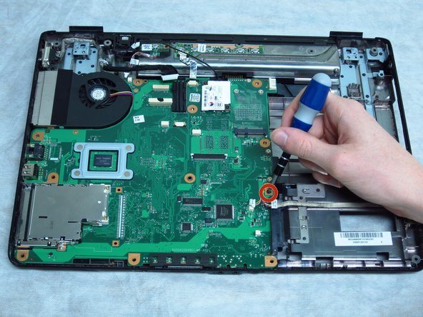
Rremove the 6-mm screw near the hard drive using a Phillips #1 screwdriver.
-
-
Этот шаг не переведен. Помогите перевести
-
Remove the two 3-mm screws from the card connected to the black wire using a Phillips #00 screwdriver.
-
-
Этот шаг не переведен. Помогите перевести
-
Gently lift the top right side of the motherboard. Pull it upwards to the right and away from you.
-


Отменить: Я не выполнил это руководство.
Еще один человек закончил это руководство.
Команда

Cal Poly, Team 3-49, Amido Spring 2013 Участник Cal Poly, Team 3-49, Amido Spring 2013
CPSU-AMIDO-S13S3G49
4 членов
Автор 19 руководств