Этот документ имеет более свежие изменения. Перейти к последней непроверенной версии.
Введение
This is a very difficult guide by the average user and is recommended to double check the power source as well as the power cable.
Выберете то, что вам нужно
-
-
If the device is still running, please turn the computer off properly and then disconnect the power supply from the power supply port in the back of the computer.
-
Remove battery before beginning any work to reduce electrical shock and to prevent damage to the electrical components.
-
Locate and slide the 2-battery locks to disconnect the battery.
-
Remove the battery by sliding it out away from the computer (horizontal with the casing).
-
-
-
Remove the RAM cover panel screws with a #1 Phillips head screwdriver as indicated in the picture, then use a flat edge tool to pry the cover off.
-
Using your fingers, push the RAM tabs that secure the RAM tabs outward (away from the RAM). The RAM should then pop up, gently remove the RAM pulling away from the connection. (Continue this process until all RAM has been removed from the device).
-
-
-
Remove the panel screw labeled with a #1 Phillips head screwdriver as indicated in the picture, then use a flat edge tool to pry the cover off.
-
The hardware to the left (labeled) can be easily removed by disconnecting the black and white wires and pushing the tabs that secure it (located on the side) outwards.
-
Pull the Wi-Fi card out from the device at a slight angle (horizontal with the casing).
-
-
-
Remove the hard drive screw labeled with a #1 Phillips head screwdriver as indicated in the picture, then use a flat edge tool to pry the cover off.
-
Using the plastic flap, grasp your hand on it and pry the hard drive out of its slot.
-
-
-
-
Remove the ODD screw with a #1 Phillips head screwdriver as indicated in the picture.
-
Using a flat edge tool, pry it the drive out of it slot from the side of the casing. You can then use your hands to continue pulling the rest the way out of its slot.
-
-
-
Using a flat edge tool begin prying off the panel above the keyboard on the side of the laptop. Perform action on both sides.
-
Turn the laptop screen so that it is horizontal with the laptop and gently remove the clips that hold this panel onto the screen hinges.
-
-
-
Remove the 2-screws on the upper outer edges of the keyboard with a #1 Phillips head screwdriver.
-
Using a flat edge tool, begin to pry the keyboard from the laptop on the upper outer edges then slowly lift the keyboard away from the laptop until you are able to remove the ribbon that connects the keyboard to the laptop.
-
-
-
Disconnect the video cable near the left speaker slowly but firmly pulling upwards.
-
Disconnect the brown ribbon that is located directly in the middle of where the keyboard one was away from the connector.
-
Disconnect the 2-other white ribbons located near the top right half of the keyboard section pulling firmly away from the connector.
-
-
-
Unscrew all the screws labeled using a micro-screwdriver turning counterclockwise.
-
There are 3-additional screws that need to be removed through the 3-holes located in the optical drive.
-
-
-
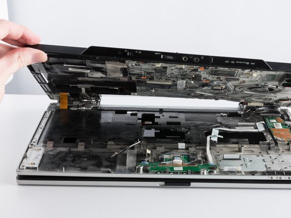
Using a flat-edge tool begin to pry away the case apart and slowly pulling upward as there is a white ribbon that need to be removed.
-
Make sure to completely untape the largest white ribbon, and let it slide through the top half of the case as you lift it.
-
-
-
Unscrew the 2-screws located above the power button logic board with a #1 Phillips head screwdriver.
-
Using a flat edge tool, and your index finger began to slowly move the logic board out of it's slot.
-
Disconnect the white ribbon connected to the power button logic board, pulling firmly and steadily.
-
Reverse the order after installing the new power button logic board.
-


To reassemble your device, follow these instructions in reverse order.
To reassemble your device, follow these instructions in reverse order.
Команда

UMass Dartmouth, Team 1-3, Cichon Spring 2014 Участник UMass Dartmouth, Team 1-3, Cichon Spring 2014
UMASSD-CICHON-S14S1G3
3 членов
Автор 1 руководств