Эта версия возможно содержит некорректные исправления. Переключить на последнюю проверенную версию.
Выберете то, что вам нужно
-
Этот шаг не переведен. Помогите перевести
-
Remove the single Phillips screw securing the hard drive bracket to the chassis.
-
-
Этот шаг не переведен. Помогите перевести
-
Lift the hard drive by its pull tab enough to grab and remove the retaining bracket.
-
Lift the hard drive out of the chassis, minding the cable attaching it to the computer.
-
-
Этот шаг не переведен. Помогите перевести
-
Remove the hard drive from its cable by pulling the cable connector straight away from the drive.
-
-
Этот шаг не переведен. Помогите перевести
-
Remove the four 10.3 mm Phillips screws securing the mid wall to the upper case.
-
-
Этот шаг не переведен. Помогите перевести
-
Remove the following three screws securing the fan to the upper case:
-
Two 5 mm Phillips screws.
-
One 7 mm Phillips screw.
-
-
Этот шаг не переведен. Помогите перевести
-
Use a spudger to pry the fan connector straight up and out of its socket on the logic board.
-
-
Этот шаг не переведен. Помогите перевести
-
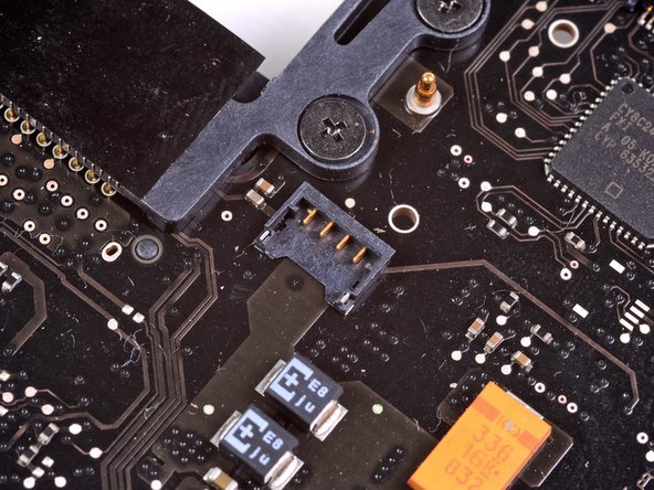
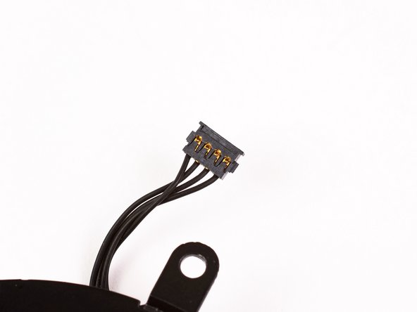
Using the flat end of a spudger, pry the subwoofer connector straight up off the logic board.
-
-
Этот шаг не переведен. Помогите перевести
-
Remove the single Phillips screw securing the subwoofer to the upper case.
-
-
Этот шаг не переведен. Помогите перевести
-
Lift the subwoofer off the optical drive, and set it above the computer.
-
-
Этот шаг не переведен. Помогите перевести
-
Use a spudger to pry the optical drive connector straight up off the logic board.
-
-
-
Этот шаг не переведен. Помогите перевести
-
Use the flat end of a spudger to pry the hard drive cable connector straight up off the logic board.
-
-
Этот шаг не переведен. Помогите перевести
-
Remove the three 2.5 mm Phillips screws securing the optical drive to the upper case.
-
-
Этот шаг не переведен. Помогите перевести
-
Lift the optical drive from its right edge and pull it out of the computer.
-
-
Этот шаг не переведен. Помогите перевести
-
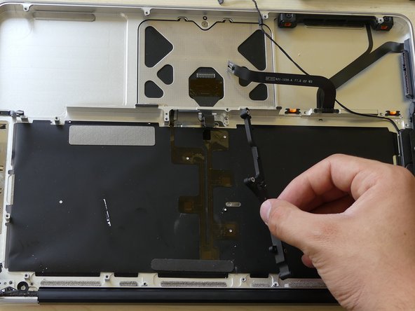
Peel the hard drive cable from the adhesive securing it to the upper case, and maneuver the plastic retaining block out of the upper case.
-
-
Этот шаг не переведен. Помогите перевести
-
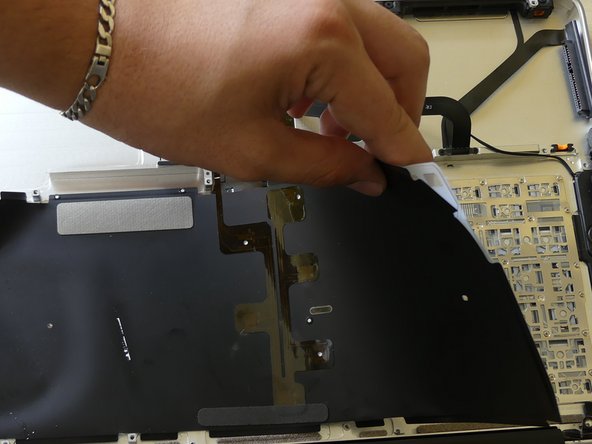
Peel back the small piece of black tape covering the right speaker cable.
-
Use the tip of a spudger to pry the right speaker up off the adhesive securing it to the upper case.
-
Lift the subwoofer and right speaker assembly out of the upper case.
-
-
Этот шаг не переведен. Помогите перевести
-
Use the tip of a spudger to flip up the locking lever to release the IR sensor ribbon cable from its socket.
-
Pull the IR sensor ribbon cable straight away from the logic board.
-
-
Этот шаг не переведен. Помогите перевести
-
Use the flat end of a spudger to pry the trackpad connector straight up off the logic board.
-
-
Этот шаг не переведен. Помогите перевести
-
Using the tip of a spudger, flip up the keyboard ribbon cable retaining flap.
-
Pull the keyboard ribbon cable straight out of its socket.
-
-
Этот шаг не переведен. Помогите перевести
-
Remove the two 5 mm Phillips screws securing the keyboard flex bracket to the upper case.
-
Lift the keyboard flex bracket out of the upper case.
-
-
Этот шаг не переведен. Помогите перевести
-
Remove the single Phillips screw securing the battery cable cover to the upper case.
-
Remove the battery cable cover from the upper case.
-
-
Этот шаг не переведен. Помогите перевести
-
Use a spudger to pry the battery level indicator cable connector straight up off the logic board.
-
-
Этот шаг не переведен. Помогите перевести
-
Disconnect the battery cable connector by pulling it straight away from the logic board.
-
-
Этот шаг не переведен. Помогите перевести
-
Remove the two 4mm Phillips screws securing the bottom case clip to the upper case.
-
Lift the bottom case clip out of the upper case.
-
-
Этот шаг не переведен. Помогите перевести
-
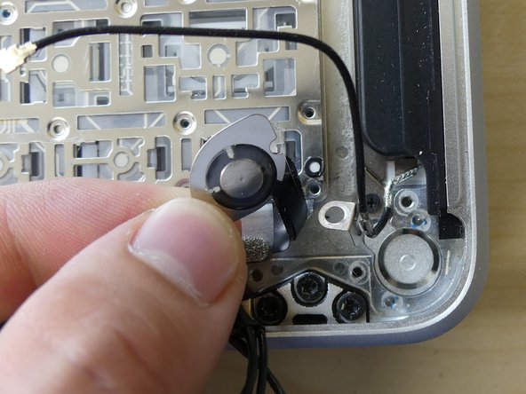
Use the tip of a spudger to release the microphone from the upper case.
-
-
Этот шаг не переведен. Помогите перевести
-
Remove the following five screws securing the logic board to the upper case:
-
Four 3 mm Phillips screws.
-
One 3.5 mm Phillips screw.
-
Remove the two 7 mm Phillips screws securing the DC-in board to the upper case.
-
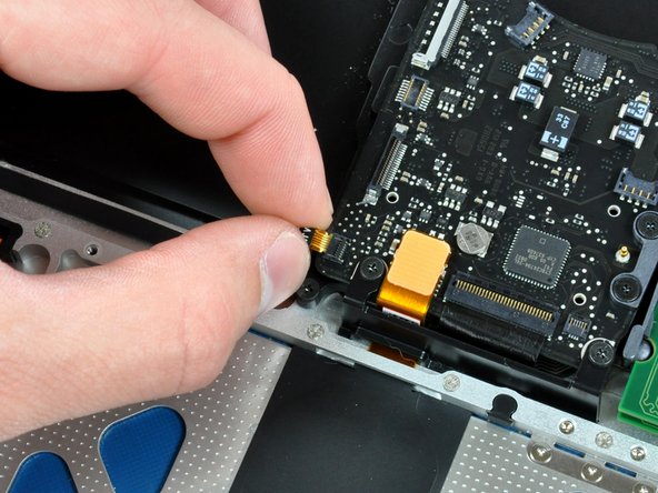
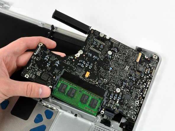
Lift the logic board from its left edge and pull it out of the upper case.
-
-
Этот шаг не переведен. Помогите перевести
-
Remove the following screws securing the battery connector cover to the upper case:
-
One 2.5 mm Phillips screw.
-
Two 1.5 mm Phillips screws.
-
Lift the battery connector cover out of the upper case.
-
-
Этот шаг не переведен. Помогите перевести
-
De-route the battery connector cable through the gap in the upper case and remove it from the computer.
-
-
Этот шаг не переведен. Помогите перевести
-
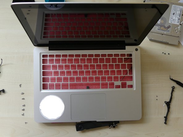
Now that you have removed the display (only required if a new top case is used to replace the keyboard), logic board, optical drive, and various other components from the upper case (or top case), you should have something that looks like this.
-
We are ready to begin!
-
-
Этот шаг не переведен. Помогите перевести
-
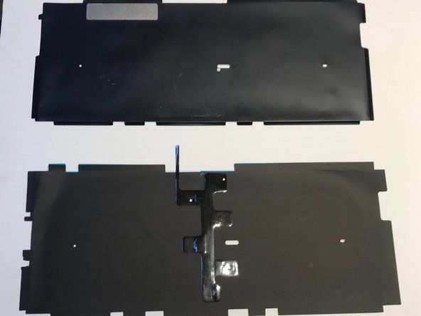
First, you'll notice the large black piece of plastic over the back of the keyboard.
-
You will need to use a spudger or a small straight edge screwdriver to carefully unstick the the edges of the plastic from the upper case.
-
-
Этот шаг не переведен. Помогите перевести
-
Now you will see a large clear plastic wafer stuck to the back of the keyboard.
-
You can remove this easily buy peeling it up slowly.
-
-
Этот шаг не переведен. Помогите перевести
-
Now that you can see the back of the individual keys, stop there.
-
After you do this, remove the power button by pressing on the power button from the top of the upper case. The power button and a small metal ring (spring) will come out.
-
-
Этот шаг не переведен. Помогите перевести
-
Now you have all probably noticed the horde of tiny black screws that cover the back of your keyboard. Yes, unfortunately we have to to take 'em out!
-
-
Этот шаг не переведен. Помогите перевести
-
Now that you have removed all of the screws, you can gently press on the face side of the keyboard and it will come right out. (If you have removed all the screws.)
-
Here is an image of the top case without its keyboard. I hope you're not winded yet. We're only half way there!
-
-
Этот шаг не переведен. Помогите перевести
-
Now you are going to install that new backlit keyboard you've always wanted!
-


Отменить: Я не выполнил это руководство.
33 участников успешно повторили данное руководство.

16 Комментариев
The photos which show how to install the backlit aren't showing. Is there maybe another thread which shows them because I can't really figure it out .
The photos aren't failing to show up, there just aren't any photos - no one ever uploaded any, even though the text of the guide talks about the pictures. As you're doing the upgrade yourself though, snap some pictures, edit the steps here, and upload your pictures!
just a question. Where exactly do I put the backlight? Because I have a black film, then a thick plastic sheet, then the metal. then the silicon layer with the components inside, and then the front black sheet, and above that you mount the keys. In between which layer do I put the backlight?
Remove black film and put your backlit
I realize that this guide is getting a bit old, but I bought just the backlight part off Ebay. It's essentially a black film with couple of leds, a clear plastic sheet and a black matte layer. It goes on top (if you look at the MB from the bottom, as in this guide) the metal layer. So it replaces the parts you remove in steps 32 and 33, after which you can start reassembling.