Введение
Follow this replacement guide to replace your control board. You will need a 3mm Allen Key and a size 1 Phillips screwdriver before starting on this venture. There are more than a few steps but this guide also overlays other guides. Such as “opening the device”, “Replacing the Display” and “Changing the Battery of the Control Board”. I would set aside time and patience for this task. You can also check out the device’s troubleshooting page VENTImotion and VENTIlogic Ventilator Troubleshooting
For more information on replacing the control board, please refer to page 39 in the service manual.
Выберете то, что вам нужно
-
-
Open the device
-
1) Place the device on a non-slip surface with the top facing downwards.
-
2) Remove the filter cassette from the top part of the housing.
-
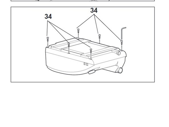
3) Undo and remove the 6 screws (34)
-
-
-
Remove the power board (see Weinmann VENTImotion and VENTIlogic Power Board Replacement)
-
-
-
Disconnect the following
-
- encoder connector (82)
-
-connectors of interfaces (84) and (85) of the control board.
-
-
-
Disconnect the ribbon cable of the display and the fascia film:
-
Pull the latch out until you feel resistance. You can then pull out the ribbon cable.
-
-
-
Insert a new battery (52) in the appropriate holder of the new control board
-
Screw on spring (54)
-
-
-
Put the control board in the top part of the housing and attach it with the four screws (51)
-
-
-
Reattach the pressure measurement hoses (57) to the pressure sensors.
-
Connect the flow sensor marked Hi to the hose connector marked Hi at the device outlet.
-
-
-
Attach the flow measurement hoses (56) to the flow sensor
-
Connect the connection of the flow sensor marked Lo to the hose connector marked Lo at the device outlet.
-
-
-
To prevent the hoses from kinking, position flow measurement hoses (56) and pressure measurement hoses (57) as shown.
-
-
-
Connect the ribbon cable for the fascia film and the display to the control board again:
-
–pull the latch upwards.
-
–push the ribbon cable into the connector.
-
–press the latch back down
-
-
-
Plug the connectors of the interfaces and the rotary knob into the appropriate slots of the control board.
-
-
-
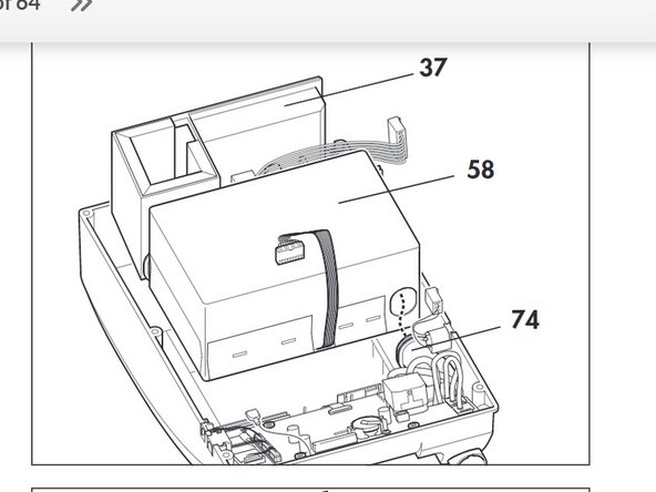
Refit the box and filter holder.
-
Connect the box and the filter holder to one another by reconnecting the intake side hose (73) from both parts.
-
Refit box (58) and filter holder (37) back on the top part of the housing together.
-
Connect the pressure-side hose (74) from the box.
-
-
-
Refit the power board Weinmann VENTImotion and VENTIlogic Power Board Replacement
-
-
-
Close the Device: Hold the bottom part of the housing (35) up to the side of the top part of the housing (36)
-
Plug the connecting cables for the humidifier (42) and the alarm (43) onto the relevant connectors.
-
Check that all hoses and cables are plugged on firmly.
-
Place the bottom part of the housing (35) on the top part of the housing (36). Ensure that no cables or hoses are trapped or bent.
-
Now screw the top part of the housing tight using the 6 screws (34).
-
Then turn the device back over
-
-
-
Test the device.
-
Page 13 of the VENTImotion & VENTIlogic Service and Repair Instructions will go into more detail.
-


To reassemble your device, follow these instructions in reverse order.
To reassemble your device, follow these instructions in reverse order.
Отменить: Я не выполнил это руководство.
Еще один человек закончил это руководство.
Команда

Cal Poly, Team S7-G19, Paton Spring 2020 Участник Cal Poly, Team S7-G19, Paton Spring 2020
CPSU-PATON-S20S7G19
3 членов
Автор 4 руководств