Перейти к основному содержанию

Эта версия возможно содержит некорректные исправления. Переключить на последнюю проверенную версию.

Медицинское оборудование
Ни iFixit, ни данное руководство по ремонту не одобрены и не связаны с производителем медицинского оборудования.

Выберете то, что вам нужно

  1. Этот шаг не переведен. Помогите перевести

    : шаг 1, изображение 1 из 2 : шаг 1, изображение 2 из 2
    • Unplug the AC power connection cable.

  2. Этот шаг не переведен. Помогите перевести

    : шаг 2, изображение 1 из 3 : шаг 2, изображение 2 из 3 : шаг 2, изображение 3 из 3
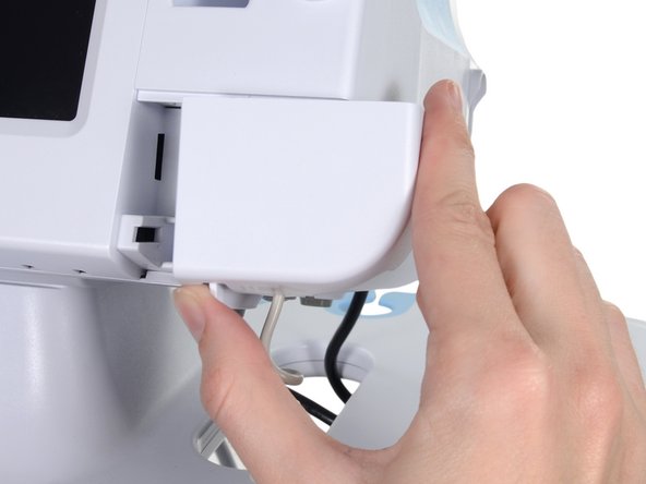
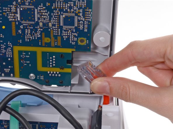
    • Place your thumb and forefinger on the blood pressure (NIBP) hose connector. Squeeze the side tabs until the connector releases.

    • Always grasp the hose by the connector. Do not pull on the hose itself.

    • Pull the connector away from the connector port.

  3. Этот шаг не переведен. Помогите перевести

    : шаг 3, изображение 1 из 3 : шаг 3, изображение 2 из 3 : шаг 3, изображение 3 из 3
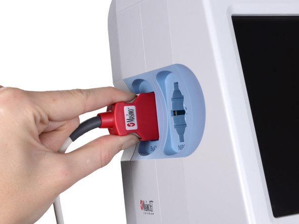
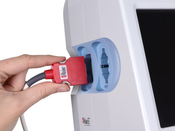
    • Place your thumb and forefinger on the Pulse oximetry (SpO2 or combined SpO2/SpHb) cable connector. Squeeze the side tabs until the connector releases.

    • Always grasp the cable by the connector. Do not pull on the cable itself.

    • Pull the connector away from the connector port.

  4. Этот шаг не переведен. Помогите перевести

    : шаг 4, изображение 1 из 2 : шаг 4, изображение 2 из 2
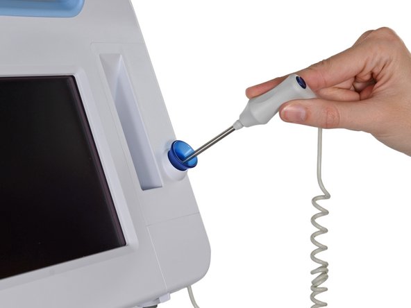
    • Grasp the temperature probe and pull it up to remove it from the monitor.

  5. Этот шаг не переведен. Помогите перевести

    : шаг 5, изображение 1 из 3 : шаг 5, изображение 2 из 3 : шаг 5, изображение 3 из 3
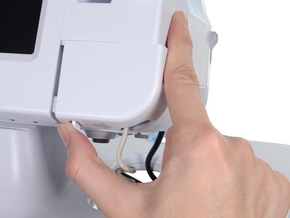
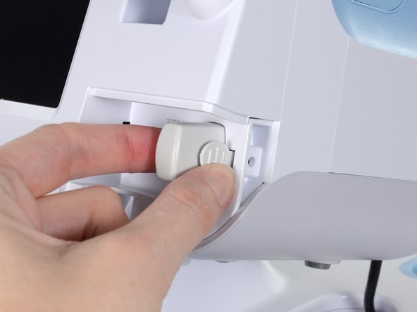
    • Remove the cover of the temperature module by pressing the tab and sliding the cover to the right.

  6. Этот шаг не переведен. Помогите перевести

    : шаг 6, изображение 1 из 3 : шаг 6, изображение 2 из 3 : шаг 6, изображение 3 из 3
    • Depress the spring tab on the temperature probe cable connector and withdraw it from the probe port.

  7. Этот шаг не переведен. Помогите перевести

    : шаг 7, изображение 1 из 1
    • Remove the flathead screw on the USB networking door.

    • Loosen the captive Phillips #2 screw securing the monitor to the stand.

  8. Этот шаг не переведен. Помогите перевести

    : шаг 8, изображение 1 из 1
    • Holding the monitor securely, open the USB networking door.

    • You may have to lift the monitor slightly to allow the door to swing out from the stand mount.

  9. Этот шаг не переведен. Помогите перевести

    : шаг 9, изображение 1 из 2 : шаг 9, изображение 2 из 2
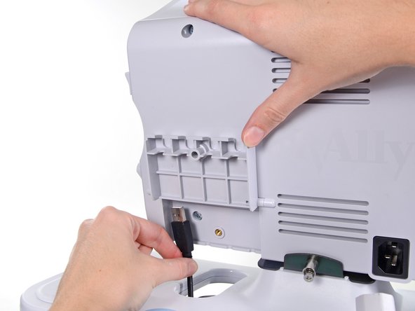
    • Detach any accessory USB cables from USB ports on the monitor.

  10. Этот шаг не переведен. Помогите перевести

    : шаг 10, изображение 1 из 3 : шаг 10, изображение 2 из 3 : шаг 10, изображение 3 из 3
    • Slide the monitor off of the stand tray.

  11. Этот шаг не переведен. Помогите перевести

    : шаг 11, изображение 1 из 3 : шаг 11, изображение 2 из 3 : шаг 11, изображение 3 из 3
    • Place the monitor upside down on a clean surface.

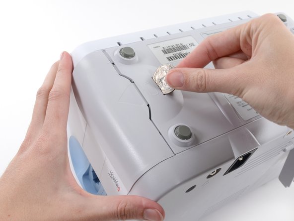
    • Insert a coin into the slot and push to open.

    • Choose a coin that fits comfortably into the slot.

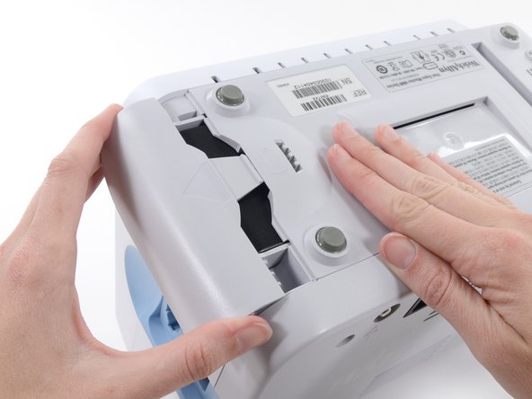
    • Remove the battery cover.

  12. Этот шаг не переведен. Помогите перевести

    : шаг 12, изображение 1 из 3 : шаг 12, изображение 2 из 3 : шаг 12, изображение 3 из 3
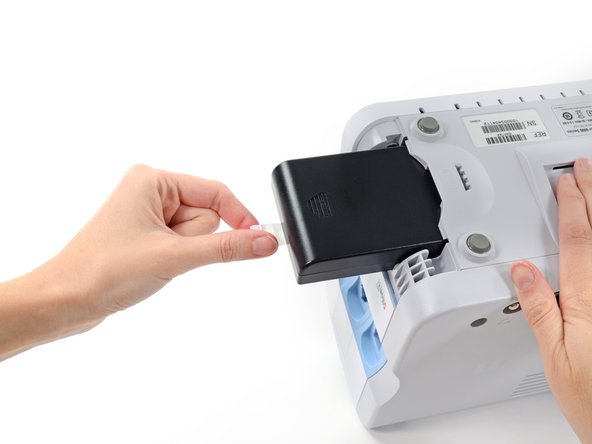
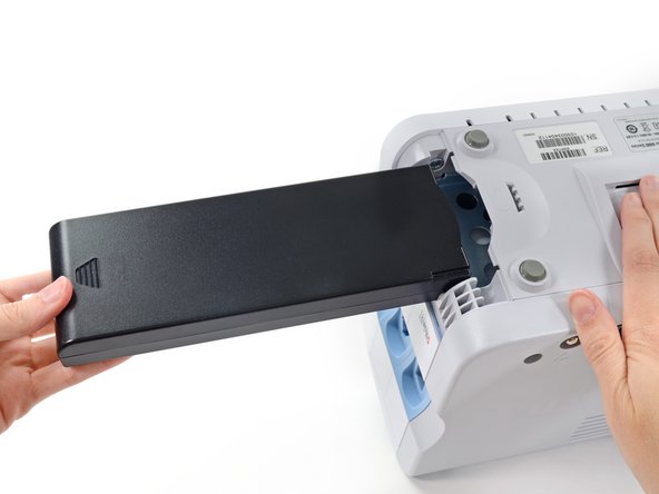
    • Use the plastic label to remove the battery from its recess.

  13. Этот шаг не переведен. Помогите перевести

    : шаг 13, изображение 1 из 2 : шаг 13, изображение 2 из 2
    • Open the communications door to access the lower left-hand rear housing screw.

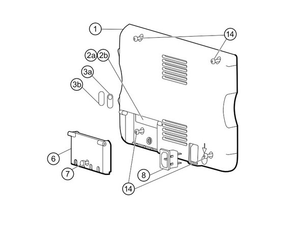
    • Remove the four Phillips #2 screws (labeled 14 in the service manual) from the rear housing.

  14. Этот шаг не переведен. Помогите перевести

    : шаг 14, изображение 1 из 2 : шаг 14, изображение 2 из 2
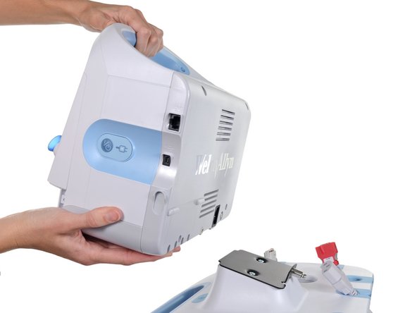
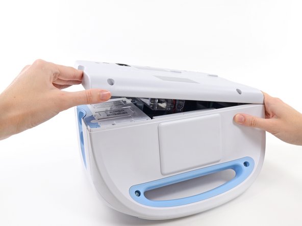
    • With the handle/alert bar facing you, begin to lift the rear housing from the left side, holding the right side securely.

    • Do not attempt to separate the rear housing from the monitor, it is still attached with several cables.

  15. Этот шаг не переведен. Помогите перевести

    : шаг 15, изображение 1 из 1
    • Support the rear housing while you disconnect the cables in the following steps.

  16. Этот шаг не переведен. Помогите перевести

    : шаг 16, изображение 1 из 3 : шаг 16, изображение 2 из 3 : шаг 16, изображение 3 из 3
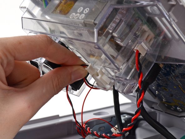
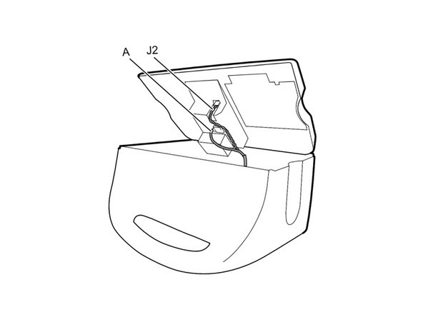
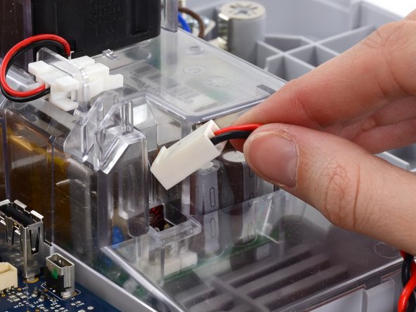
    • Disconnect the fan cable (labeled connector A in the service manual) from its socket in the power supply.

  17. Этот шаг не переведен. Помогите перевести

    : шаг 17, изображение 1 из 3 : шаг 17, изображение 2 из 3 : шаг 17, изображение 3 из 3
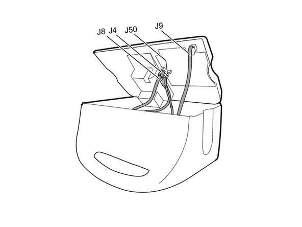
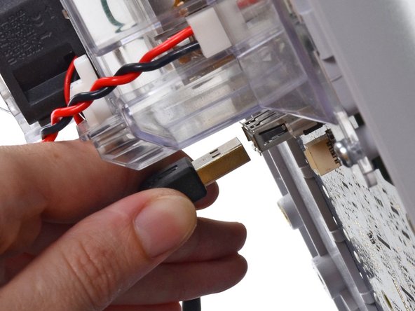
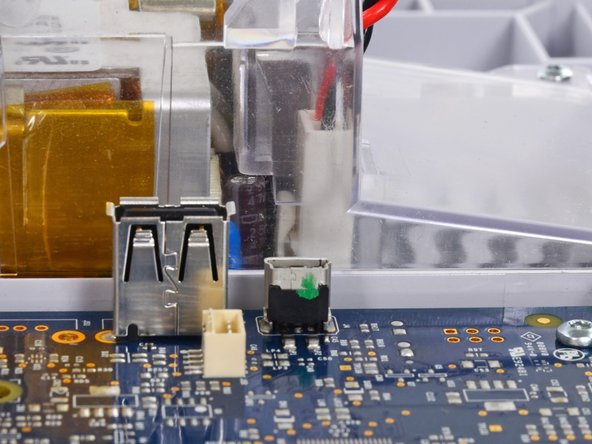
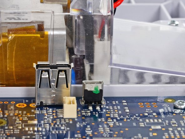
    • Unplug the small USB connector from its socket (labeled J4 in the service manual).

  18. Этот шаг не переведен. Помогите перевести

    : шаг 18, изображение 1 из 3 : шаг 18, изображение 2 из 3 : шаг 18, изображение 3 из 3
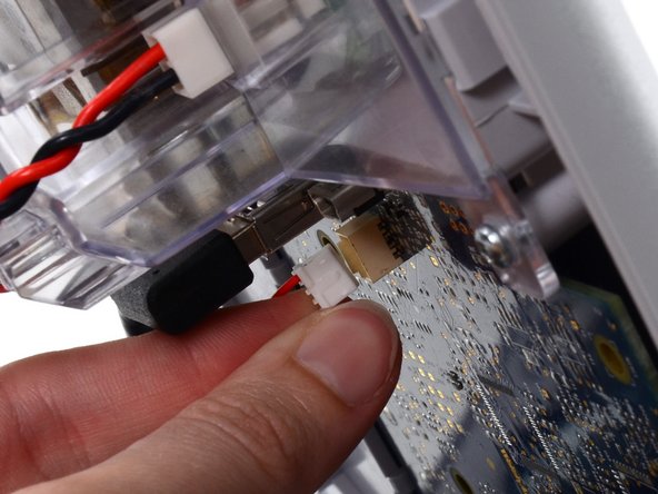
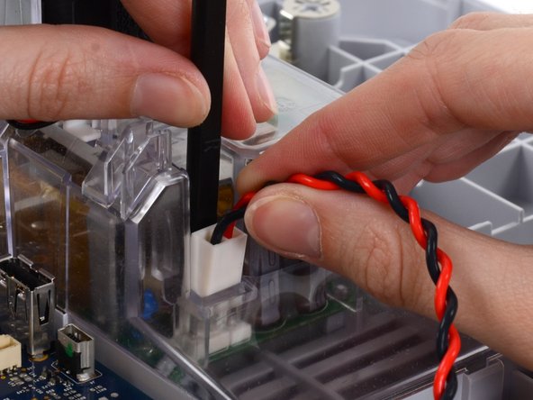
    • Disconnect the communications power cable from its socket (labeled J50 in the service manual).

    • Only pull on the connector itself and not the socket. This connection is very tight, work the connector slowly and gently.

  19. Этот шаг не переведен. Помогите перевести

    : шаг 19, изображение 1 из 3 : шаг 19, изображение 2 из 3 : шаг 19, изображение 3 из 3
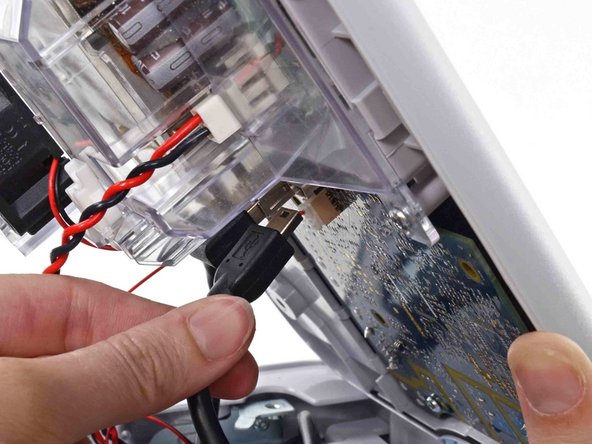
    • Unplug the large USB connector from its socket (labeled J8 in the service manual).

  20. Этот шаг не переведен. Помогите перевести

    : шаг 20, изображение 1 из 3 : шаг 20, изображение 2 из 3 : шаг 20, изображение 3 из 3
    • Press the tab on the ethernet cable and unplug it from its socket (labeled J9 in the service manual).

  21. Этот шаг не переведен. Помогите перевести

    : шаг 21, изображение 1 из 1
    • The following connector requires two hands to disconnect. Flip the rear case over, and lay it on its back to gain access to the power supply cable.

  22. Этот шаг не переведен. Помогите перевести

    : шаг 22, изображение 1 из 3 : шаг 22, изображение 2 из 3 : шаг 22, изображение 3 из 3
    • The power supply cable is secured by an interlocking connector that must be held open to unplug the connector.

    • Insert the flat end of a spudger down into the power supply cover between the socket clip and the power supply connector.

  23. Этот шаг не переведен. Помогите перевести

    : шаг 23, изображение 1 из 3 : шаг 23, изображение 2 из 3 : шаг 23, изображение 3 из 3
    • Grasp the power supply cable firmly and lift both it and the spudger from the channel in the power supply housing to unplug the connector.

Финишная черта

Еще один человек закончил это руководство.

Sam Goldheart

Участник с: 10/18/12

465 854 Репутация

Автор 538 руководств

Команда

iFixit Участник iFixit

Staff

135 членов

Автор 17 198 руководств

0 Комментариев

Добавить комментарий

Просмотр статистики:

За последние 24часов: 2

За последние 7 дней: 7

За последние 30 дней: 14

За всё время: 622