Эта версия возможно содержит некорректные исправления. Переключить на последнюю проверенную версию.
Выберете то, что вам нужно
-
Этот шаг не переведен. Помогите перевести
-
Use the tip of a spudger to remove the black rubber screw cover from the side of the PS3.
-
-
Этот шаг не переведен. Помогите перевести
-
Remove the single 8.5 mm T10 Security Torx screw from the smart plate.
-
-
Этот шаг не переведен. Помогите перевести
-
Pull the smart plate toward the hard drive bay, then lift it off the body of the PS3.
-
-
Этот шаг не переведен. Помогите перевести
-
Remove the following seven screws:
-
Six 52 mm Phillips screws
-
One 30 mm Phillips screw
-
-
Этот шаг не переведен. Помогите перевести
-
Lift the top cover from its rear edge and rotate it toward the front of the PS3.
-
Remove the top cover.
-
There is a plastic hook located in a hole on the top back right hand side corner. Carefully push the plastic hook a bit from the rear of the machine with a spudger to release the rear right of the casing.
-
-
Этот шаг не переведен. Помогите перевести
-
Lift the Blu-ray drive from the edge nearest the power supply and rotate it away from the chassis enough to access its ribbon cable.
-
-
Этот шаг не переведен. Помогите перевести
-
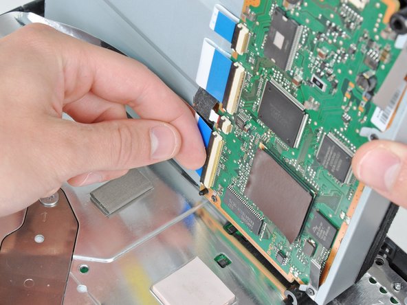
Use your fingernail to flip up the retaining flap on the Blu-ray ribbon cable socket.
-
Pull the ribbon cable out of its socket.
-
Remove the Blu-ray drive from the PS3.
-
-
Этот шаг не переведен. Помогите перевести
-
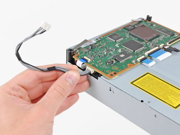
Pull the control board ribbon cable straight up and out of its socket on the motherboard.
-
-
Этот шаг не переведен. Помогите перевести
-
Remove the two 12 mm Phillips screws securing the control board to the lower case.
-
Remove the control board and its attached cable from the PS3.
-
-
Этот шаг не переведен. Помогите перевести
-
Remove the following eight screws securing the motherboard assembly to the lower case:
-
Seven 12 mm Phillips screws (ph2)
-
One 30 mm Phillips screw
-
-
Этот шаг не переведен. Помогите перевести
-
Use the flat end of a spudger to pry the hard drive bay cover away from the lower case.
-
Remove the hard drive bay cover.
-
-
Этот шаг не переведен. Помогите перевести
-
Remove the 7.7 mm Phillips screw securing the ground strap to the chassis.
-
-
Этот шаг не переведен. Помогите перевести
-
Pull the AC-In cables slightly away from the rear cover for clearance to access the AC-In connector.
-
While depressing its locking mechanism, pull the AC-In connector out of its socket on the power supply.
-
-
-
Этот шаг не переведен. Помогите перевести
-
Pull the AC inlet out from the bottom of the rear cover, minding any of its cables that may get caught.
-
-
Этот шаг не переведен. Помогите перевести
-
While lightly pulling the rear cover away from the logic board assembly, use the flat end of a spudger to release the clips along the top and bottom edges of the rear cover.
-
-
Этот шаг не переведен. Помогите перевести
-
De-route the fan cables from the plastic finger molded into the heat sink.
-
Disconnect the fan from the motherboard.
-
-
Этот шаг не переведен. Помогите перевести
-
Remove the two 9 mm Phillips screws securing the memory card reader to the chassis.
-
-
Этот шаг не переведен. Помогите перевести
-
Lift the memory card reader out of the PS3 enough to access its ribbon cable.
-
Flip up the retaining flap on the memory card reader ribbon cable socket.
-
Pull the ribbon cable out of its socket and remove the memory card reader.
-
-
Этот шаг не переведен. Помогите перевести
-
Disconnect the DC-In cables from the front of the heat sink.
-
-
Этот шаг не переведен. Помогите перевести
-
Remove the five 9 mm Phillips screws securing the power supply to the chassis.
-
-
Этот шаг не переведен. Помогите перевести
-
Lift the power supply by its front edge to clear the two posts attached to the motherboard.
-
Remove the power supply.
-
-
Этот шаг не переведен. Помогите перевести
-
Remove the four 16.5 mm shouldered Phillips screws securing the heat sink to the motherboard.
-
Remove the two brackets held under the screws you just removed.
-
-
Этот шаг не переведен. Помогите перевести
-
Lift the motherboard assembly off the heat sink.
-
Be sure to apply a new layer of thermal paste when reattaching the heat sink.
-
-
Этот шаг не переведен. Помогите перевести
-
Flip up the retaining flap on the Blu-ray ribbon cable socket.
-
Remove the Blu-ray ribbon cable.
-
-
Этот шаг не переведен. Помогите перевести
-
Flip up the flap on the memory card reader ribbon cable socket and remove the ribbon cable.
-
-
Этот шаг не переведен. Помогите перевести
-
Flip up the retaining flap on the Wi-Fi/Bluetooth ribbon cable socket.
-
Pull the Wi-Fi/Bluetooth ribbon cable out of its socket.
-
-
Этот шаг не переведен. Помогите перевести
-
Disconnect the DC-In cable from the motherboard and set it aside.
-
-
Этот шаг не переведен. Помогите перевести
-
Rotate the PRAM battery slightly counter-clockwise and remove it from the motherboard assembly.
-
-
Этот шаг не переведен. Помогите перевести
-
Remove the blue 8 mm Phillips screw securing the hard drive cage to the chassis.
-
-
Этот шаг не переведен. Помогите перевести
-
Push the hard drive cage toward the front of the motherboard assembly.
-
Remove the hard drive from the motherboard assembly.
-
-
Этот шаг не переведен. Помогите перевести
-
Remove the two 3.7 mm #0 Phillips screws securing the chassis to the hard drive socket.
-
-
Этот шаг не переведен. Помогите перевести
-
Remove the two 8.3 mm #0 Phillips screws securing the two halves of the motherboard together.
-
-
Этот шаг не переведен. Помогите перевести
-
Carefully feed the Wi-Fi/Bluetooth ribbon cable through the hole in the top motherboard cover.
-
Remove the top motherboard cover.
-
-
Этот шаг не переведен. Помогите перевести
-
Flip up the retaining flap on the Wi-Fi/Bluetooth ribbon cable socket.
-
Remove the Wi-Fi/Bluetooth ribbon cable from the motherboard.
-
Motherboard remains.
-
-
Этот шаг не переведен. Помогите перевести
-
Using the flat end of the spudger, remove the old thermal paste off the CPU and GPU on the motherboard.
-
Using a cleaner such as Arctic Silver's ArctiClean or high alcohol content rubbing alcohol, clean the CPU and GPU.
-
-
Этот шаг не переведен. Помогите перевести
-
Using your fingers or the flat end of a spudger, remove the old thermal pads on the logic board as indicated:
-
Large square thermal pads
-
Small square thermal pads
-
Small rectangular thermal pads (located on the underside of the board, as highlighted in the second picture)
-
-
Этот шаг не переведен. Помогите перевести
-
Set the heat gun to "Low" or around 300C (575F), and let it run for a few seconds to reach operating temperature.
-
Holding the motherboard upright, warm up the entire board with the heat gun. The board should be warm, but not too hot.
-
-
Этот шаг не переведен. Помогите перевести
-
Set the motherboard on a support so that the CPU and GPU are completely supported and level.
-
-
Этот шаг не переведен. Помогите перевести
-
Using a circular motion, evenly heat (using low heat) the two processors labeled "RSX" and "CELL" for 2 minutes while keeping the gun about 1/2" above the chip. For the Lower two areas heat for 30 seconds following the same distance guidelines from above.
-
Begin heating the GPU, marked "RSX", and heat the chips in a zig-zag order.
-
-
Этот шаг не переведен. Помогите перевести
-
Continue heating the chips using the same circular motion as described above, for about 25 seconds each.
-
-
Этот шаг не переведен. Помогите перевести
-
If you have not applied thermal paste before you can check our thermal paste guide whilst it is cooling.
-
Apply a thin bead of thermal paste on the CPU.
-
Using the thermal paste spreader card, spread the paste out thinly and evenly on the chip.
-
In the same way, apply a thin layer of thermal paste on the GPU.
-
Clean up any excess thermal paste off the motherboard.
-
-
Этот шаг не переведен. Помогите перевести
-
Apply the fresh thermal pads to the motherboard in the locations indicated:
-
Large square pads
-
Small square pads
-
Small Rectangular Pads
-
Two 3cm x 3cm Squares
-
Ten 1cm x 1cm Squares
-
Five 1.5cm x 0.5cm rectangles
-
-
Этот шаг не переведен. Помогите перевести
-
Peel the remaining white plastic cover off the other side of thermal pads.
-


Отменить: Я не выполнил это руководство.
1256 участников успешно повторили данное руководство.


224 Комментариев
Done this twice, first time it lasted 2 weeks and the second time 10 days. I'll do it one more time and if it goes again, I think I'll be buying a new console.
Great repair guide, clear and simple -I don't know why it's rated as difficult -there's no soldering or wiring to do.
great repaier guiad
hamza -
I completed this repair last night. It wasn't as hard as I thought, though it did take me almost 3 hours to accomplish. My PS3 is back up and running, and the fan is so guiet not I can hardly hear it.
I will add that these pictures provided are from a 60GB launch PS3. I have an 80GB (MGS4 Bundle), and some of the inner workings are a little different. The card reader remains attached to the upper casing, and the ground wire for the A/C switch is run under the power supply... as opposed to over it as it is in this guide.
Overall, this is a great guide and the kit was a great price. I hope my PS3 will remain operational at least through Christmas... I've got my eye on the UC3 Bundle; )
This is an excellent guide! I've had the YLOD before about a year ago, and my brother shipped it off to get it fixed for me (his COD:MW2 was stuck inside). It cost him $150 to get it repaired because the warranty had run out. While it did work for an entire year after the repair (which is very surprising with most people saying theirs only worked for about a month after getting it fixed), I definitely don't think all that money was worth it. I am extremely pleased that I was able to fix it myself with absolutely no cost to me (I borrowed a heat gun and thermal paste from a friend). No cost is way better than $150 obviously. I do intend to sell my PS3 to Gamestop though and buy a new slim, which I hear is less likely to get the YLOD due to better cooling. I will most likely open it up at replace the thermal paste though, as I've heard the paste Sony uses is very cheap, along with a few modifications for better cooling.
--------------
Long story short, this guide just saved me $150 dollars. Also, my PS3 is the 60GB backwards compatible if that is of interest to anyone.