Эта версия возможно содержит некорректные исправления. Переключить на последнюю проверенную версию.
Выберете то, что вам нужно
-
Этот шаг не переведен. Помогите перевести
-
Use a coin to rotate the battery locking screw 90 degrees clockwise.
-
Lift the battery out of the computer.
-
-
Этот шаг не переведен. Помогите перевести
-
Pull the keyboard release tabs toward you and lift up on the keyboard until it pops free.
-
If the keyboard does not come free, use a small flathead screwdriver to turn the keyboard locking screw 180 degrees in either direction and try again.
-
Flip the keyboard over, away from the screen, and rest it face-down on the trackpad area.
-
-
Этот шаг не переведен. Помогите перевести
-
Push the wire clasp toward the Airport card and pull it up to free it from the RAM shield.
-
-
Этот шаг не переведен. Помогите перевести
-
Grasp the clear plastic tab on the Airport card and pull toward the right.
-
-
Этот шаг не переведен. Помогите перевести
-
Hold the Airport card in one hand and use your other hand to remove the antenna cable.
-
-
Этот шаг не переведен. Помогите перевести
-
Remove the two 2.5 mm Phillips screws that secure the RAM shield.
-
-
Этот шаг не переведен. Помогите перевести
-
Grasp the metal bracket on top of the RAM shield and pull upward to remove the shield.
-
-
Этот шаг не переведен. Помогите перевести
-
Pull the keyboard cable up from the logic board, holding the cable as close to the connector as possible.
-
-
Этот шаг не переведен. Помогите перевести
-
Use a pin (or anything you like) to remove the three rubber feet from the lower case.
-
-
Этот шаг не переведен. Помогите перевести
-
Use a spudger or small flathead screwdriver to pry up the three metal rings that housed the rubber bumpers.
-
-
Этот шаг не переведен. Помогите перевести
-
Remove the one 10 mm and two 20 mm hex screws using a 2mm hex. Alternatively, a T8 Torx screwdriver key will do.
-
-
Этот шаг не переведен. Помогите перевести
-
Remove the two 4.2 mm Phillips screws on either side of the battery contacts.
-
-
Этот шаг не переведен. Помогите перевести
-
Breathe deeply. Trying times are ahead, but we promise the lower case does come off.
-
Push the thin rims of the lower case surrounding the battery compartment in, bending them past the tabs, and then lift up to free that corner of the lower case.
-
-
Этот шаг не переведен. Помогите перевести
-
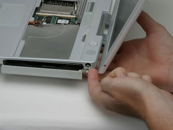
There is a slot on the wall of the battery compartment that locks the lower case in place. Use a small flathead screwdriver to pry out the slot's lower rim and pull up on the lower case to free the slot from the tabs holding it.
-
-
Этот шаг не переведен. Помогите перевести
-
Run a spudger along the seam between the lower case and upper case on the front of the computer to free the tabs locking the lower case. Pull up on the lower case and continue to use the spudger as necessary until you hear three distinct clicks.
-
-
Этот шаг не переведен. Помогите перевести
-
Continue to run the spudger around the front, right corner. There are two tabs on the port side of the computer, one near the front corner and one near the sound out port.
-
-
Этот шаг не переведен. Помогите перевести
-
Once the front and sides of the lower case are free, turn the computer so that the back is facing you and pull the lower case up and toward you until the back tabs pop free (it may be helpful to jiggle the case up and down).
-
-
Этот шаг не переведен. Помогите перевести
-
Remove the small greasy springs with white plastic caps from either side of the battery contacts.
-
-
Этот шаг не переведен. Помогите перевести
-
Remove the following 4 screws on the bottom of the computer:
-
Two 3 mm Phillips from the left side of the computer.
-
One 4.5 mm Phillips near the latch mechanism (this screw may be missing in 800 MHz iBooks)
-
One 14.2 mm Phillips near the front, right corner.
-
-
Этот шаг не переведен. Помогите перевести
-
Use a straightened paperclip to open the optical drive tray.
-
-
Этот шаг не переведен. Помогите перевести
-
Pull the optical drive out just enough so that you can access and remove a Phillips screw near the battery compartment.
-
-
-
Этот шаг не переведен. Помогите перевести
-
Pull the optical drive a bit more so that you can access and remove a second Phillips screw near the power receptacle.
-
-
Этот шаг не переведен. Помогите перевести
-
Turn over the computer and open it.
-
Use tweezers (or a refrigerator magnet) to remove the magnet covering a Phillips screw near the middle of the computer.
-
-
Этот шаг не переведен. Помогите перевести
-
Remove the following 4 screws on the edges of the keyboard area.
-
One 4.5 mm Phillips underneath where the magnet was.
-
Three 6 mm Phillips in plastic depressions.
-
-
Этот шаг не переведен. Помогите перевести
-
Peel up the foil tape covering the speaker cable near the ports.
-
-
Этот шаг не переведен. Помогите перевести
-
1) With your fingernails, grasp the locking bar on either side and pull up a small amount (about 1/16" or 2 mm).
-
2) After disengaging the locking bar, slide the cable out of the connector.
-
-
Этот шаг не переведен. Помогите перевести
-
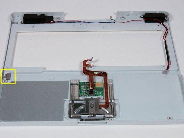
Loosen the trackpad connector by pulling the top piece up slightly, freeing the trackpad ribbon.
-
Slide the orange trackpad ribbon out of the connector.
-
-
Этот шаг не переведен. Помогите перевести
-
Lift the upper case from the left side and use your other hand to pull out the right side in order to clear the power receptacle.
-
-
Этот шаг не переведен. Помогите перевести
-
Lift the upper case enough to disconnect the blue and white power cable from the logic board. Using your fingernails or a dental pick, carefully pry the connector from its socket. Make sure you're pulling only on the connector and not on the socket.
-
-
Этот шаг не переведен. Помогите перевести
-
Lift the upper case off completely and disconnect the red and black speaker cable from the logic board. As before, make sure you're pulling only on the connector and not on the socket.
-
-
Этот шаг не переведен. Помогите перевести
-
Remove the following 14 screws (some models may be missing a couple of screws):
-
One 2.5 mm Phillips.
-
Six 3.5 mm Phillips.
-
One 4.5 mm Phillips near the sleep light with a small shaft.
-
Two 4.5 mm Phillips with larger shafts.
-
Four 5 mm Phillips
-
If a screw is inserted in the left hole, the 14.2 mm screw in step 24 can not be inserted to hold the top case down.
-
-
Этот шаг не переведен. Помогите перевести
-
Peel back three strips of yellow tape in the bottom left corner.
-
Peel back one strip of foil tape in the upper left corner and another near where the trackpad connects to the logic board.
-
-
Этот шаг не переведен. Помогите перевести
-
Lift the top shield up from the right side, minding the upper left corner, which may catch on the metal framework.
-
-
Этот шаг не переведен. Помогите перевести
-
Disconnect the microphone cable from the front, left corner of the logic board.
-
Peel back the black tape and free the microphone cable from the hard drive.
-
-
Этот шаг не переведен. Помогите перевести
-
Use the black plastic handle to disconnect the display data cable from the logic board.
-
-
Этот шаг не переведен. Помогите перевести
-
Remove the single Phillips securing the display data cable to the metal framework.
-
-
Этот шаг не переведен. Помогите перевести
-
Peel back the yellow tape securing the inverter cable to the optical drive.
-
-
Этот шаг не переведен. Помогите перевести
-
Carefully deroute the inverter cable from beneath the optical drive.
-
Deroute the Airport antenna cable from beneath the optical drive.
-
-
Этот шаг не переведен. Помогите перевести
-
Remove the single Phillips screw on the outer edge of either hinge (two screws total).
-
Tilt the display back to get over two small nubbins, and then slide it directly from the case and away.
-
-
Этот шаг не переведен. Помогите перевести
-
Use a 1.5mm hex screwdriver to remove the two hex screws on either side of the display (four screws total).
-
-
Этот шаг не переведен. Помогите перевести
-
Use your thumbs to slightly separate the rear bezel from the front bezel.
-
-
Этот шаг не переведен. Помогите перевести
-
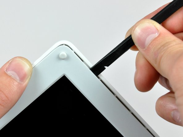
Insert the flat end of a spudger into the gap between the front and rear bezels.
-
Rotate your spudger until it is parallel to the front face of the display.
-
Run the spudger around the perimeter of the display to separate the rear bezel from its retaining clips.
-
-
Этот шаг не переведен. Помогите перевести
-
Remove the large piece of tape near the lower right corner of the display.
-
-
Этот шаг не переведен. Помогите перевести
-
Remove the single screw inserted through the piece of EMI tape near the bottom edge of the display (it's the first of the two clutch cover screws).
-
Use the tip of a spudger to remove the small washer under the screw you just removed.
-
-
Этот шаг не переведен. Помогите перевести
-
Peel the aluminum/EMI tape as one piece off the cast aluminum frame of the clutch hinges.
-
-
Этот шаг не переведен. Помогите перевести
-
Remove the pieces of readily removable tape from around the perimeter of the display.
-
-
Этот шаг не переведен. Помогите перевести
-
Remove the piece of aluminum tape near the center of the LCD cover.
-
Peel back the piece of tape securing the display data cable ground loop to the thin steel LCD cover.
-
-
Этот шаг не переведен. Помогите перевести
-
Remove the two Phillips screws securing each side of the LCD to the clutch hinge frame (four screws total).
-
-
Этот шаг не переведен. Помогите перевести
-
Remove the second of the two Phillips screws securing the clutch cover to the cast aluminum frame of the clutch hinges.
-
-
Этот шаг не переведен. Помогите перевести
-
Remove the two pieces of tape over the display data/microphone cables near the lower edge of the display.
-
-
Этот шаг не переведен. Помогите перевести
-
Use the tip of a spudger to lift the microphone out of the front bezel.
-
De-route the microphone cable from around the top and side of the display.
-
-
Этот шаг не переведен. Помогите перевести
-
Disconnect the display data cable by pulling its connector away from the socket on the LCD.
-
Remove the display data cable from the display.
-
-
Этот шаг не переведен. Помогите перевести
-
Remove the two pieces of tape covering the inverter/AirPort cables along the lower edge of the display.
-
-
Этот шаг не переведен. Помогите перевести
-
Use the flat end of a spudger to push the backlight connector while gently pulling its cables away from the socket on the inverter.
-
Lift the LCD out of the front bezel and set it aside.
-
-
Этот шаг не переведен. Помогите перевести
-
Remove the three Phillips screws securing the reed switch board and the AirPort antenna to the front bezel.
-
De-route the reed switch/AirPort antenna cables around the side of the display.
-
-
Этот шаг не переведен. Помогите перевести
-
Gently peel the inverter cable ground strap off the cast aluminum frame of the clutch hinges.
-
While pulling the inverter cable away from its socket on the inverter board, use the tip of a spudger to push the connector out of its socket.
-
-
Этот шаг не переведен. Помогите перевести
-
Remove the two Phillips screws securing the AirPort antenna to the front bezel.
-
De-route the AirPort antenna cable along the edge of the display.
-
-
Этот шаг не переведен. Помогите перевести
-
If you have a 1.33 GHz 12" G4 iBook, simply remove the Inverter/AirPort cables.
-
For all other models, use the flat end of a spudger to remove the antenna board from the front bezel.
-
Remove the inverter/AirPort cables.
-


Отменить: Я не выполнил это руководство.
8 участников успешно повторили данное руководство.
Прикрепленные документы

3 Комментариев
Excellent guide.
I have been through about half of this, replacing a failed hard disk. After an hour or so, it's like "You gotta be kidding me..."
If it makes you feel any better, this iBook disassembly is easier than its sibling, the lampshade iMac.