Эта версия возможно содержит некорректные исправления. Переключить на последнюю проверенную версию.
Выберете то, что вам нужно
-
Этот шаг не переведен. Помогите перевести
-
Loosen the two Phillips screws securing the access door to your iMac.
-
-
Этот шаг не переведен. Помогите перевести
-
Remove the three T8 Torx screws securing the front bezel to the rear panel.
-
-
Этот шаг не переведен. Помогите перевести
-
Use your thumbs to press both RAM arms in past the front bezel for enough clearance to lift it off the rear case.
-
-
Этот шаг не переведен. Помогите перевести
-
While holding the RAM arms in with your thumbs, lift the lower edge of the front bezel enough to clear the rear case.
-
-
Этот шаг не переведен. Помогите перевести
-
Insert a plastic card up into the corner of the air vent slot at the top of the rear case.
-
Push the card toward the top of the iMac to release the front bezel latch.
-
Pull the front bezel away from the rear case.
-
Repeat this process for the other side of the front bezel.
-
-
Этот шаг не переведен. Помогите перевести
-
Lay your iMac stand-side down on a table.
-
Lift the front bezel from its lower edge and rotate it away from the rest of your iMac, minding the RAM arms that may get caught.
-
Lay the front bezel above the rest of the iMac.
-
-
Этот шаг не переведен. Помогите перевести
-
If necessary, remove the piece of kapton tape wrapped around the microphone and camera cables.
-
-
Этот шаг не переведен. Помогите перевести
-
Peel back the aluminum EMI shield up off the lower three edges of the rear case.
-
-
Этот шаг не переведен. Помогите перевести
-
Remove the two 5 mm T6 Torx screws securing the display data cable to the logic board.
-
Using its attached black tab, pull the display data cable connector up off the logic board.
-
-
Этот шаг не переведен. Помогите перевести
-
Pull the inverter cable connector up off its socket on the logic board.
-
-
Этот шаг не переведен. Помогите перевести
-
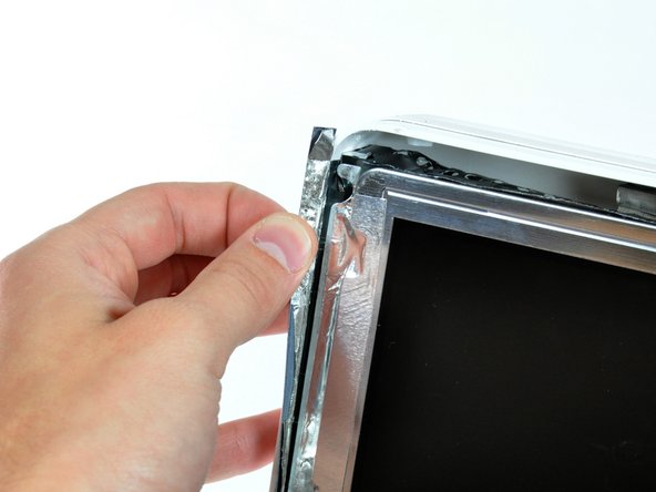
Peel back the aluminum EMI tape from the two vertical edges of the display.
-
-
Этот шаг не переведен. Помогите перевести
-
Remove the four recessed coarse-thread 7.5 mm T10 Torx screws securing the display to the rear case.
-
-
Этот шаг не переведен. Помогите перевести
-
Lift the display from its lower edge and pull it toward yourself to peel it off the EMI shield attached to its top edge.
-
-
-
Этот шаг не переведен. Помогите перевести
-
Remove the single 5 mm T6 Torx screw securing the IR board bracket to the logic board.
-
Remove the IR cable finger and move the IR board, with cable still attached, out of the way.
-
-
Этот шаг не переведен. Помогите перевести
-
Remove the single 30 mm T10 Torx screw securing the left speaker to the rear case.
-
Pull the left speaker out of the rear case.
-
-
Этот шаг не переведен. Помогите перевести
-
De-route the left speaker cable along its path across the logic board.
-
-
Этот шаг не переведен. Помогите перевести
-
Remove the single 17 mm T10 Torx screw securing the right speaker to the logic board.
-
Lift the right speaker out of the rear case and move it out of the way.
-
-
Этот шаг не переведен. Помогите перевести
-
If necessary, lift the IR board cable to free the left speaker cable pinned beneath.
-
Pull the speaker connector toward the top edge of your iMac to disconnect it from the logic board.
-
-
Этот шаг не переведен. Помогите перевести
-
Disconnect the CPU fan connector from the logic board by pulling it straight up from its socket.
-
-
Этот шаг не переведен. Помогите перевести
-
Disconnect the following connectors from the logic board by pulling them straight up from their sockets.:
-
Ambient light sensor cable.
-
Power cable.
-
-
Этот шаг не переведен. Помогите перевести
-
Disconnect the hard drive data cable connector from the logic board by pulling it straight up from its socket.
-
-
Этот шаг не переведен. Помогите перевести
-
De-route the IR sensor cable from behind the AirPort Express card and set it aside.
-
-
Этот шаг не переведен. Помогите перевести
-
Remove two 5 mm T6 Torx screws securing the AirPort/Bluetooth board to the logic board.
-
Lift the AirPort/Bluetooth board up from its left edge to separate it from its socket on the logic board.
-
-
Этот шаг не переведен. Помогите перевести
-
Use the flat end of a spudger to pry both antenna cables up off the AirPort/Bluetooth board.
-
This step need not be done. Simply lay the card over the side.
-
-
Этот шаг не переведен. Помогите перевести
-
Disconnect the camera board cable connector from the logic board by pulling it straight away from its socket.
-
-
Этот шаг не переведен. Помогите перевести
-
Disconnect the optical drive fan cable connector from the logic board by pulling it straight away from its socket.
-
-
Этот шаг не переведен. Помогите перевести
-
Remove the 7 mm T10 Torx screw securing the optical drive flex cable mounting bracket to the logic board.
-
Remove the flex cable mounting bracket.
-
-
Этот шаг не переведен. Помогите перевести
-
Disconnect the optical drive flex cable from the logic board by pulling it straight up from its socket.
-
-
Этот шаг не переведен. Помогите перевести
-
De-route the hard drive data cable and tuck it under the optical drive to prevent the cable from interfering with future steps.
-
-
Этот шаг не переведен. Помогите перевести
-
Disconnect the hard drive fan connector from the logic board by pulling it straight away from its socket.
-
-
Этот шаг не переведен. Помогите перевести
-
Use the tip of a spudger to lift the hard drive and optical drive thermal sensor cables for clearance.
-
Disconnect the optical drive temperature sensor connector from the logic board by pulling it straight away from its socket.
-
-
Этот шаг не переведен. Помогите перевести
-
Disconnect the hard drive temperature sensor connector from the logic board by pulling it straight away from its socket.
-
-
Этот шаг не переведен. Помогите перевести
-
Remove the following screws securing the logic board to the rear case:
-
Four fine threaded 7 mm T10 Torx screws.
-
Three coarse threaded 7 mm T10 Torx screws.
-
-
Этот шаг не переведен. Помогите перевести
-
Push the two RAM arms protruding from the access door inward and set them on the lower edge of the rear case to prevent them from getting caught when removing the logic board.
-
-
Этот шаг не переведен. Помогите перевести
-
Grab the logic board and pull it toward yourself slightly to separate the jacks from the rear case.
-
Rotate the top of the logic board toward yourself slightly to gain access to the DC power cable connector.
-
-
Этот шаг не переведен. Помогите перевести
-
While grasping the logic board with one hand, disconnect the DC power cable connector from the logic board by pulling it straight away from its socket.
-
-
Этот шаг не переведен. Помогите перевести
-
Lift the hard drive fan off the plastic posts protruding from the rear case.
-
-
Этот шаг не переведен. Помогите перевести
-
Use a pair of tweezers to pull the AC-in cable out from underneath the chassis.
-
-
Этот шаг не переведен. Помогите перевести
-
Disconnect the AC-in cable connector by depressing the lock mechanism while pulling the connector away from its socket.
-
-
Этот шаг не переведен. Помогите перевести
-
Use a spudger to peel back the three pieces of EMI tape covering the AC power inlet.
-
-
Этот шаг не переведен. Помогите перевести
-
Remove the following screws securing the AC power inlet to the rear case:
-
Three T10 Torx screws
-
One T10 Torx screw securing the ground cable.
-
-
Этот шаг не переведен. Помогите перевести
-
De-route the AC-in cable connector from under the chassis and remove the AC power inlet from your iMac.
-


Отменить: Я не выполнил это руководство.
2 участников успешно повторили данное руководство.
