Эта версия возможно содержит некорректные исправления. Переключить на последнюю проверенную версию.
Выберете то, что вам нужно
-
Этот шаг не переведен. Помогите перевести
-
Loosen the single Phillips screw in the center of the access door.
-
Remove the access door from your iMac.
-
-
Этот шаг не переведен. Помогите перевести
-
Stick two suction cups to opposing corners of the glass panel.
-
-
-
Этот шаг не переведен. Помогите перевести
-
Remove the following 12 screws securing the front bezel to the rear case:
-
Eight 13 mm T8 Torx.
-
Four 25 mm T8 Torx.
-
-
Этот шаг не переведен. Помогите перевести
-
Place your hands at the top corners of the bezel (to the side) and lift the bezel 2-3cm from the body by working from the top. After this you can also disengage the bottom of the bezel (the memory modules will prevent the bottom of the bezel to detach first). When reassembling, start with the bottom of the bezel.
-
To fully detach the bezel: disconnect the microphone cable connector, removing tape as necessary.
-
To keep it attached, leave the microphone cable attached to the logic board, and place the bezel 'above' the chassis, with the microphone cable forming a hinge.
-
-
Этот шаг не переведен. Помогите перевести
-
be sure to tuck the microphone cable and connector into the void next to the camera board.
-
Gently guide the microphone connector and cables through the ±1in long slot at the right of the iSight camera. Once the bezel is properly assembled, gently push the microphone connector and cable into the bezel through that slot.
-
-
Этот шаг не переведен. Помогите перевести
-
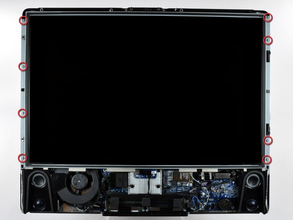
After removing the front bezel, you need to remove the 8ea 12mm T8 screws around the perimeter of the LCD
-
-
Этот шаг не переведен. Помогите перевести
-
Use the chart provided as a reference and test the various voltages with your meter being sure to restrict the probes to the 10 solder joints on the PSU connector shown within the BLUE rectangle. Shorting any part of the PCB will almost certainly cause damage to the imac
-
All voltage measurements are taken with PIN 1 as reference (Marked with the YELLOW square). Pin 1 is marked on the board by a dot and is the right hand pin when viewed as shown in photos
-
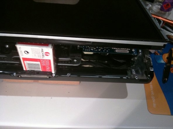
Reassemble your iMac in reverse order. When lowering the LCD ensure you don't crimp or crush the LCD back-light cables
-


Отменить: Я не выполнил это руководство.
20 участников успешно повторили данное руководство.

Команда

10 Комментариев
Something I don't get…
I'm investigating on my mid2007 iMac power problems and I don't get the same results of voltage as in this article. In my case, number 9 is at around 12V and number 8 is at 0V.
Is my PSU really faulty or there might be some other PSU models?
I've got the same results as you. Wondering if we have the wrong ps model, despite being what iFixit recommends and sells. Very odd.
i have the same issue. Do we have the wrong power supply or the wrong voltage chart?
Have also the same, maybe the table here is wrong. What kind of problems does your mac have?