Перейти к основному содержанию

Эта версия возможно содержит некорректные исправления. Переключить на последнюю проверенную версию.

Выберете то, что вам нужно

  1. Этот шаг не переведен. Помогите перевести

    : шаг 1, изображение 1 из 1
    Инструмент, используемый на этом этапе:
    iMac Intel 21.5" Cardboard Service Wedge
    $4.99
    Купить
    • With the hinge free to move, the iMac will be unbalanced and hard to work on. Repairs can be completed as shown, but are faster and easier with an iMac service wedge.

    • If you are using the iFixit cardboard service wedge, follow these assembly directions to put it together.

    • Before beginning any work on your iMac: Unplug the computer and press and hold the power button for ten seconds to discharge the power supply's capacitors.

    • Be very careful not to touch the capacitor leads or any exposed solder joints on the back of the power supply. Only handle the board by the edges.

  2. Этот шаг не переведен. Помогите перевести

    : шаг 2, изображение 1 из 2 : шаг 2, изображение 2 из 2
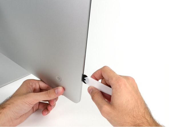
    • Starting on the left of the display, near the power button, insert the iMac Opening Tool into the gap between the glass panel and the rear enclosure.

    • The hub on the iMac Opening Tool will keep you from pushing the wheel in too far. If using a different tool, insert no more than 3/8" into the display. Otherwise, you risk severing antenna cables and causing serious damage.

    • Be gentle! The glass may crack if pried too much. Use a hairdryer to heat the edges and loosen the tape if the room temperatures are low.

  3. Этот шаг не переведен. Помогите перевести

    : шаг 3, изображение 1 из 3 : шаг 3, изображение 2 из 3 : шаг 3, изображение 3 из 3
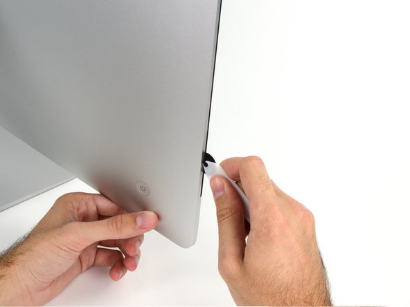
    • Use the tool like a pizza cutter—roll it along through the gap, and it will cut the foam adhesive through the center.

    • Be sure to always push with the handle behind the cutting wheel. If you pull, the wheel might get pulled out of the handle.

    • Run the tool up along the left side of the display.

  4. Этот шаг не переведен. Помогите перевести

    : шаг 4, изображение 1 из 3 : шаг 4, изображение 2 из 3 : шаг 4, изображение 3 из 3
    • Continue running the tool up around the top left corner.

  5. Этот шаг не переведен. Помогите перевести

    : шаг 5, изображение 1 из 2 : шаг 5, изображение 2 из 2
    • Cut the adhesive along the top left of the display.

  6. Этот шаг не переведен. Помогите перевести

    : шаг 6, изображение 1 из 2 : шаг 6, изображение 2 из 2
    • Continue along the top of the display.

    • You may want to run the tool back and forth through what you've already cut a few times, to ensure you get as much of the adhesive separated as possible.

  7. Этот шаг не переведен. Помогите перевести

    : шаг 7, изображение 1 из 3 : шаг 7, изображение 2 из 3 : шаг 7, изображение 3 из 3
    • Push the tool around the top right corner of the display.

  8. Этот шаг не переведен. Помогите перевести

    : шаг 8, изображение 1 из 2 : шаг 8, изображение 2 из 2
    • Wheel the tool down along the right side of the display.

  9. Этот шаг не переведен. Помогите перевести

    : шаг 9, изображение 1 из 2 : шаг 9, изображение 2 из 2
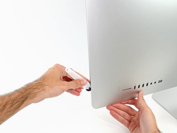
    • Finish pushing the opening tool to the bottom of the right side of the display.

    • At this point, you'll want to run the tool back around the entire display, to ensure you cut as much adhesive as possible.

  10. Этот шаг не переведен. Помогите перевести

    : шаг 10, изображение 1 из 3 : шаг 10, изображение 2 из 3 : шаг 10, изображение 3 из 3
    Инструмент, используемый на этом этапе:
    Plastic Cards
    $2.99
    Купить
    • While the opening tool cut most of the adhesive, the display will still be slightly adhered to the case. A plastic card will be necessary to free up the last of this adhesive.

    • Set the iMac face-up on a table.

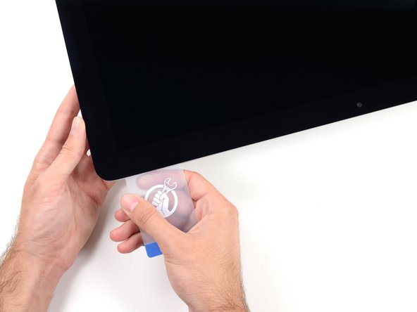
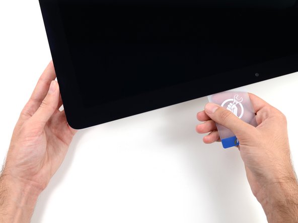
    • Starting from the top right corner of the iMac, wedge a plastic card between the display and frame.

    • Be careful not to insert the plastic card more than 3/8", or you may damage internal components.

  11. Этот шаг не переведен. Помогите перевести

    : шаг 11, изображение 1 из 2 : шаг 11, изображение 2 из 2
    • Gently twist the plastic card sideways to create a gap between the display and frame.

    • Move slowly and be careful not to stress the display glass too much—you only need to make a gap of about 1/4".

  12. Этот шаг не переведен. Помогите перевести

    : шаг 12, изображение 1 из 3 : шаг 12, изображение 2 из 3 : шаг 12, изображение 3 из 3
    • Slide the card toward the center of the display to cut any of the remaining adhesive along the top right corner of the iMac.

    • Be sure to stop before the iSight camera, or you may damage it.

  13. Этот шаг не переведен. Помогите перевести

    : шаг 13, изображение 1 из 2 : шаг 13, изображение 2 из 2
    • Wedge the plastic card into the top right corner once again and let it stay there to keep the adhesive from resettling.

  14. Этот шаг не переведен. Помогите перевести

    : шаг 14, изображение 1 из 3 : шаг 14, изображение 2 из 3 : шаг 14, изображение 3 из 3
    • Insert a second plastic card into the gap between the display and frame located at the top left corner of the iMac.

  15. Этот шаг не переведен. Помогите перевести

    : шаг 15, изображение 1 из 2 : шаг 15, изображение 2 из 2
    • Gently twist the card upward, slightly increasing the space between the display and frame.

    • As with the other side, twist slowly to allow the adhesive time to separate, and be careful not to over-stress the display glass.

  16. Этот шаг не переведен. Помогите перевести

    : шаг 16, изображение 1 из 3 : шаг 16, изображение 2 из 3 : шаг 16, изображение 3 из 3
    • Slide the plastic card toward the center, again stopping just before the iSight camera.

  17. Этот шаг не переведен. Помогите перевести

    : шаг 17, изображение 1 из 2 : шаг 17, изображение 2 из 2
    • Wedge the plastic card back into the top left corner.

  18. Этот шаг не переведен. Помогите перевести

    : шаг 18, изображение 1 из 3 : шаг 18, изображение 2 из 3 : шаг 18, изображение 3 из 3
    • With both plastic cards inserted as shown near the corners, gently twist the cards sideways to increase the gap between display and case.

    • If there are any sections that seem to stick and won't separate, stop twisting and use one of the cards to cut the remaining adhesive.

    • Begin to lift the top of the display up from the frame.

    • Only lift the display a few inches—the display data and power cables are still connected to the logic board.

  19. Этот шаг не переведен. Помогите перевести

    : шаг 19, изображение 1 из 2 : шаг 19, изображение 2 из 2
    • While holding the display up with one hand, use the other hand to unplug the display power cable. Make sure that you pull the cable out from the plastic tab, and not by pulling on the color wires.

    • Lift the display up enough to have easy access to the connector, but not so much that you stretch the cables and stress their connections (about 8").

  20. Этот шаг не переведен. Помогите перевести

    : шаг 20, изображение 1 из 3 : шаг 20, изображение 2 из 3 : шаг 20, изображение 3 из 3
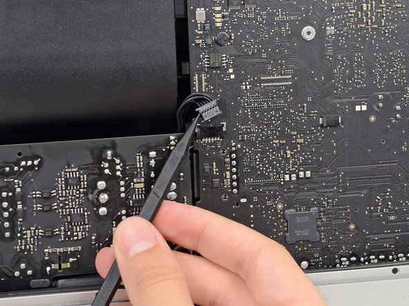
    • Use the tip of a spudger to flip up the metal retaining bracket on the display data cable.

    • Carefully pull the display data cable from its socket on the logic board.

    • Be sure to pull the display data cable connector straight out of its socket.

  21. Этот шаг не переведен. Помогите перевести

    : шаг 21, изображение 1 из 2 : шаг 21, изображение 2 из 2
    • Lift the display up to a near-vertical position.

    • At this point there is still a strip of adhesive along the bottom of the display, that will hold the display to the frame like a hinge. You can loosen this adhesive by working the display up and down a few times.

  22. Этот шаг не переведен. Помогите перевести

    : шаг 22, изображение 1 из 3 : шаг 22, изображение 2 из 3 : шаг 22, изображение 3 из 3
    • Be very careful not to touch the capacitor leads or any exposed solder joints on the back of the power supply (boxed in red).

    • Grasp the small tab at the end of one of the bottom edge display adhesive strips and pull the adhesive toward the top of the iMac to remove it.

    • Repeat this step with the other adhesive strip and remove it.

    • If either adhesive strip breaks before it's removed, use a plastic card to slice through the remaining adhesive.

  23. Этот шаг не переведен. Помогите перевести

    : шаг 23, изображение 1 из 3 : шаг 23, изображение 2 из 3 : шаг 23, изображение 3 из 3
    • Lift the display up from the frame and remove it from the iMac.

    • It may be necessary to slowly lift from one side, to peel against the remaining adhesive.

    • Be very careful handling the display—it's big, heavy, and made of glass.

    • During reassembly, head over to our display adhesive guide to install the new adhesive.

  24. Этот шаг не переведен. Помогите перевести

    : шаг 24, изображение 1 из 2 : шаг 24, изображение 2 из 2
    • Remove the following five Phillips screws holding the lower support bracket in place:

    • Four 3.2 mm screws

    • One 1.7 mm screw

    • On at least some EMC 2544 machines, all five screws are the same size.

    • You may need to peel up the display adhesive lining the bottom edge of the iMac enclosure to access the screws.

  25. Этот шаг не переведен. Помогите перевести

    : шаг 25, изображение 1 из 1
    • Remove the lower support bracket from the iMac enclosure.

  26. Этот шаг не переведен. Помогите перевести

    : шаг 26, изображение 1 из 2 : шаг 26, изображение 2 из 2
    • Use a spudger to loosen the right speaker cable's connector from its socket on the logic board.

    • It is useful to push downward on both short sides of the connector to "walk" it out of its socket. Be careful with the corners of the connectors, they can be easily broken off.

    • Pull the connector downwards to remove it from its socket.

  27. Этот шаг не переведен. Помогите перевести

    : шаг 27, изображение 1 из 1
    • Remove the two 10.0 mm T10 screws securing the right speaker to the rear enclosure.

  28. Этот шаг не переведен. Помогите перевести

    : шаг 28, изображение 1 из 2 : шаг 28, изображение 2 из 2
    • Pull the top of the right speaker away from the rear enclosure, about half an inch, to expose the antenna cable running down its right side.

  29. Этот шаг не переведен. Помогите перевести

    : шаг 29, изображение 1 из 3 : шаг 29, изображение 2 из 3 : шаг 29, изображение 3 из 3
    • Insert the tip of a spudger between the right speaker and the antenna cable that is routed into the speaker's right side.

    • Run the spudger down along the right side of the speaker to pry the antenna cable from its channel in the right speaker.

  30. Этот шаг не переведен. Помогите перевести

    : шаг 30, изображение 1 из 3 : шаг 30, изображение 2 из 3 : шаг 30, изображение 3 из 3
    • Pull the right speaker straight up about an inch, toward the top of the iMac.

    • Lift the right speaker straight up and remove it from the iMac. This may take some force, both hands and rocking the speaker right and left to get it out.

  31. Этот шаг не переведен. Помогите перевести

    : шаг 31, изображение 1 из 1
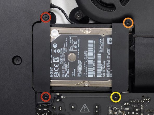
    • Remove the following screws securing the hard drive bracket to the rear enclosure:

    • Two 21 mm T10 Torx screws from the left-hand hard drive bracket.

    • One 9 mm T10 Torx screw.

    • One 27 mm T10 Torx screw.

  32. Этот шаг не переведен. Помогите перевести

    : шаг 32, изображение 1 из 2 : шаг 32, изображение 2 из 2
    • Remove the left and right hard drive brackets from the iMac.

  33. Этот шаг не переведен. Помогите перевести

    : шаг 33, изображение 1 из 3 : шаг 33, изображение 2 из 3 : шаг 33, изображение 3 из 3
    • The next few steps bring your hands close to the exposed face of the power supply. Do not touch the face of the power supply to avoid a high voltage shock from the many large capacitors attached to the board.

    • Use the tip of a spudger to push each side of the power button cable connector and gently "walk" it out of its socket.

  34. Этот шаг не переведен. Помогите перевести

    : шаг 34, изображение 1 из 2 : шаг 34, изображение 2 из 2
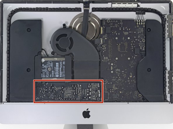
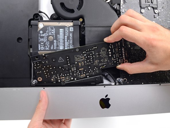
    • Gently push upward on each side of the power supply control cable connector with the tip of a spudger to gently "walk" it out of its socket.

  35. Этот шаг не переведен. Помогите перевести

    : шаг 35, изображение 1 из 1
    • Remove the two 7.2 mm T10 screws securing the power supply to the rear enclosure.

  36. Этот шаг не переведен. Помогите перевести

    : шаг 36, изображение 1 из 2 : шаг 36, изображение 2 из 2
    • When working on the power supply, be very careful not to touch the capacitor leads or any exposed solder joints on the back of the power supply. Only handle the board by the edges.

    • Tilt the power supply forward.

  37. Этот шаг не переведен. Помогите перевести

    : шаг 37, изображение 1 из 3 : шаг 37, изображение 2 из 3 : шаг 37, изображение 3 из 3
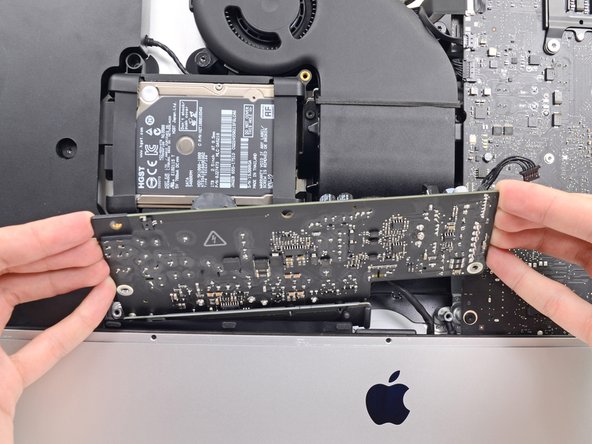
    • Pull the power supply slightly up and out from the rear enclosure.

    • Rotate the power supply counterclockwise, lifting the right side up about an inch higher than the left.

  38. Этот шаг не переведен. Помогите перевести

    : шаг 38, изображение 1 из 2 : шаг 38, изображение 2 из 2
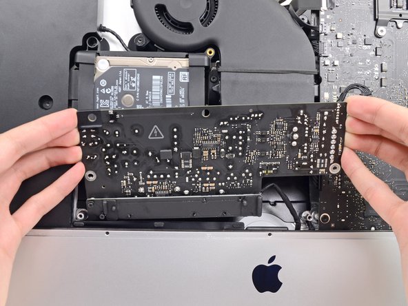
    • Slide the power supply to the right to clear the screw posts on the rear enclosure.

  39. Этот шаг не переведен. Помогите перевести

    : шаг 39, изображение 1 из 3 : шаг 39, изображение 2 из 3 : шаг 39, изображение 3 из 3
    • Rock the power supply forward and remove it from its recess in the rear enclosure.

    • Do not try to completely remove the power supply from the iMac yet—it is still connected to the logic board.

  40. Этот шаг не переведен. Помогите перевести

    : шаг 40, изображение 1 из 2 : шаг 40, изображение 2 из 2
    • Be very careful not to touch the capacitor leads or any exposed solder joints on the back of the power supply. Only handle the board by the edges.

    • Flip the top of the power supply towards you to access the DC power cable connection behind the logic board.

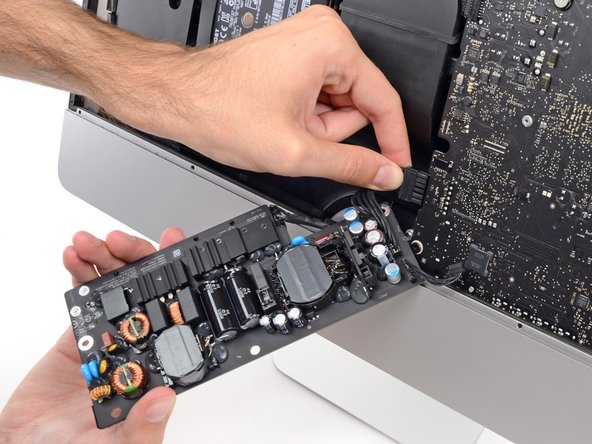
    • Squeeze the DC power cable connector tab and pull it straight out of its socket on the back of the logic board.

  41. Этот шаг не переведен. Помогите перевести

    : шаг 41, изображение 1 из 3 : шаг 41, изображение 2 из 3 : шаг 41, изображение 3 из 3
    • You may find it helpful to set the iMac down on its back on the table for the next couple of steps.

    • Use the flat end of a spudger to push the clip on the side of the AC inlet cable connector inward.

    • While holding on the release clip with the spudger, grasp the AC inlet cable, and pull the connector straight out of its socket.

  42. Этот шаг не переведен. Помогите перевести

    : шаг 42, изображение 1 из 1
    • Remove the power supply from the iMac.

  43. Этот шаг не переведен. Помогите перевести

    : шаг 43, изображение 1 из 2 : шаг 43, изображение 2 из 2
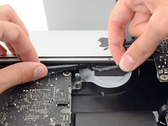
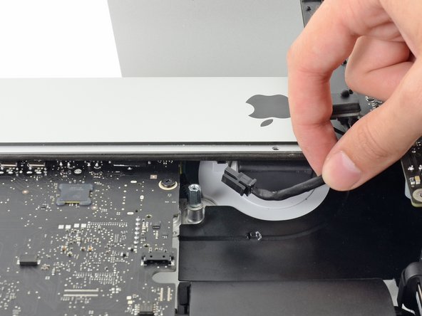
    • Gently pull the fan cable connector straight away from its socket on the logic board.

  44. Этот шаг не переведен. Помогите перевести

    : шаг 44, изображение 1 из 1
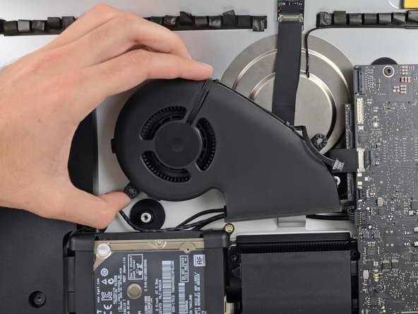
    • Remove the three 12.3 mm T10 shoulder screws securing the fan to the rear enclosure.

  45. Этот шаг не переведен. Помогите перевести

    : шаг 45, изображение 1 из 2 : шаг 45, изображение 2 из 2
    • Remove the fan from the iMac.

  46. Этот шаг не переведен. Помогите перевести

    : шаг 46, изображение 1 из 3 : шаг 46, изображение 2 из 3 : шаг 46, изображение 3 из 3
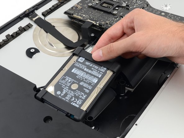
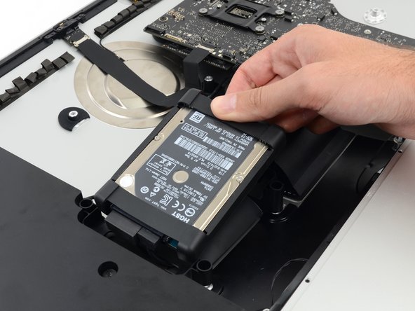
    • Lift the hard drive from the edge nearest the logic board and pull it slightly out of its recess.

    • The hard drive is attached by two cables, do not attempt to fully remove it from the iMac.

  47. Этот шаг не переведен. Помогите перевести

    : шаг 47, изображение 1 из 2 : шаг 47, изображение 2 из 2
    • Disconnect the SATA power cable.

  48. Этот шаг не переведен. Помогите перевести

    : шаг 48, изображение 1 из 2 : шаг 48, изображение 2 из 2
    • Unplug the SATA data cable from the hard drive.

  49. Этот шаг не переведен. Помогите перевести

    : шаг 49, изображение 1 из 1
    • Remove the hard drive from the iMac.

  50. Этот шаг не переведен. Помогите перевести

    : шаг 50, изображение 1 из 1
    • Remove the single 7.2 mm T10 screw securing the hard drive tray to the rear enclosure.

  51. Этот шаг не переведен. Помогите перевести

    : шаг 51, изображение 1 из 1
    • Remove the hard drive tray from the rear enclosure.

  52. Этот шаг не переведен. Помогите перевести

    : шаг 52, изображение 1 из 2 : шаг 52, изображение 2 из 2
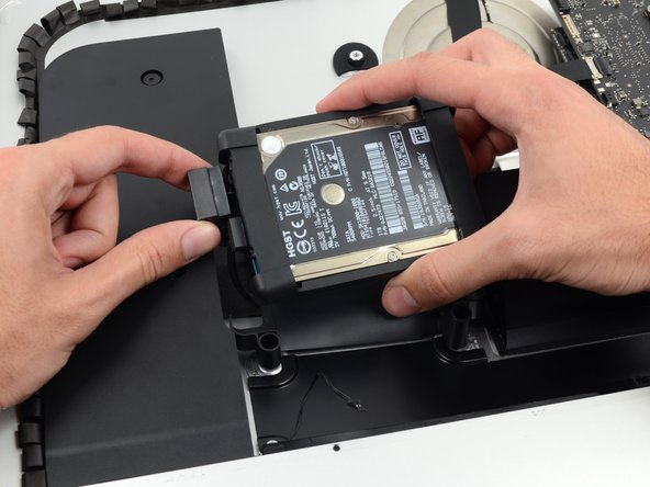
    • Push on each side of the left speaker cable connector with the tip of a spudger and gently "walk" it out of its socket.

  53. Этот шаг не переведен. Помогите перевести

    : шаг 53, изображение 1 из 2 : шаг 53, изображение 2 из 2
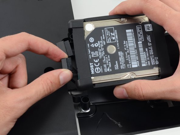
    • De-route the left speaker cable by pulling it straight up out of the retaining clip in the back of the rear enclosure.

  54. Этот шаг не переведен. Помогите перевести

    : шаг 54, изображение 1 из 3 : шаг 54, изображение 2 из 3 : шаг 54, изображение 3 из 3
    • In a similar fashion as the previous step, de-route the SATA data and power cables up out of the retaining clip.

  55. Этот шаг не переведен. Помогите перевести

    : шаг 55, изображение 1 из 3 : шаг 55, изображение 2 из 3 : шаг 55, изображение 3 из 3
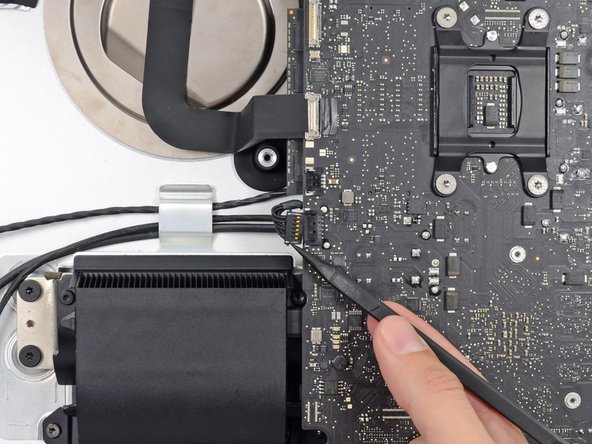
    • Use the flat edge of a spudger to flip up the metal retaining bracket on the iSight camera cable connector.

    • Pull the iSight camera cable straight out of its socket on the logic board.

    • This is a delicate connector that can be easily damaged.

  56. Этот шаг не переведен. Помогите перевести

    : шаг 56, изображение 1 из 3 : шаг 56, изображение 2 из 3 : шаг 56, изображение 3 из 3
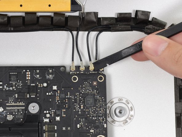
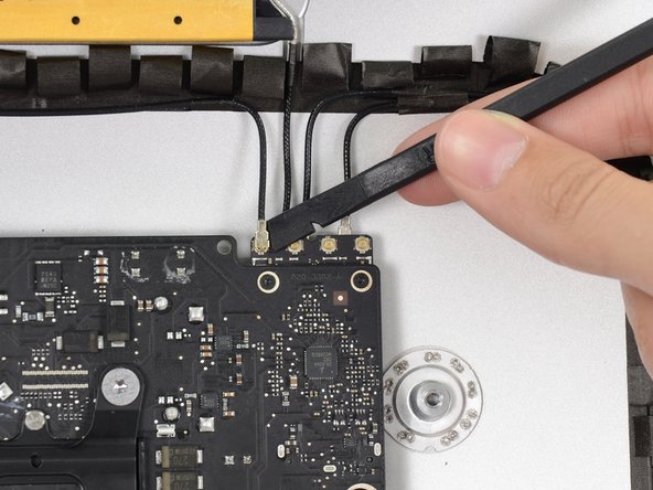
    • Use the flat edge of a spudger to disconnect each of the four antenna connectors from the AirPort/Bluetooth card.

    • Note the original positions for each connector when reconnecting the cables.

  57. Этот шаг не переведен. Помогите перевести

    : шаг 57, изображение 1 из 1
    • If brackets secure the four antenna cables, remove the two T5 Torx screws from the brackets.

  58. Этот шаг не переведен. Помогите перевести

    : шаг 58, изображение 1 из 3 : шаг 58, изображение 2 из 3 : шаг 58, изображение 3 из 3
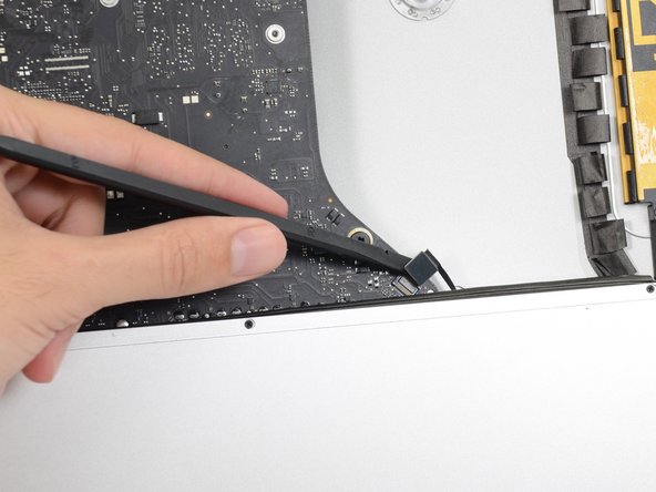
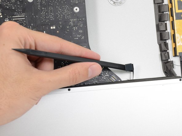
    • Use the flat edge of a spudger to pry the headphone jack cable connector from its socket on the logic board.

    • Push the cable slightly to the right.

  59. Этот шаг не переведен. Помогите перевести

    : шаг 59, изображение 1 из 1
    • Remove the following screws securing the exhaust duct to the rear enclosure:

    • Two 6.3 mm T8 screws

    • Two 4.7 mm T8 screws

  60. Этот шаг не переведен. Помогите перевести

    : шаг 60, изображение 1 из 1
    • Remove the four 7.2 mm T10 screws securing the logic board to the rear enclosure.

    • Depending on the age and model of your iMac, a T9 driver may work best.

  61. Этот шаг не переведен. Помогите перевести

    : шаг 61, изображение 1 из 3 : шаг 61, изображение 2 из 3 : шаг 61, изображение 3 из 3
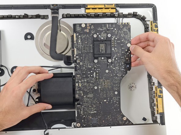
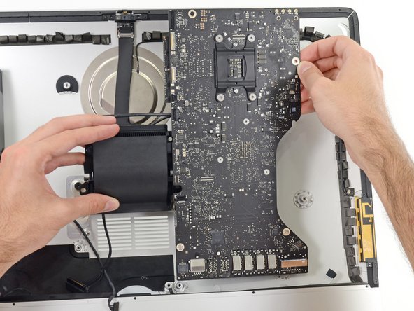
    • Tilt the top of the logic board away from the rear enclosure.

    • Lift the logic board straight up and out of the iMac.

    • Be careful not to snag the board on any of the rear case's screw posts.

    • The I/O boards at the bottom of the logic board will be the greatest challenge. It is recommended to pull gently to avoid any damage.

    • During reassembly of the logic board, pay attention to the position of the I/O connectors. When the board is back in the case, insert a USB or Thunderbolt cable into one of the connectors to align it perfectly.

  62. Этот шаг не переведен. Помогите перевести

    : шаг 62, изображение 1 из 3 : шаг 62, изображение 2 из 3 : шаг 62, изображение 3 из 3
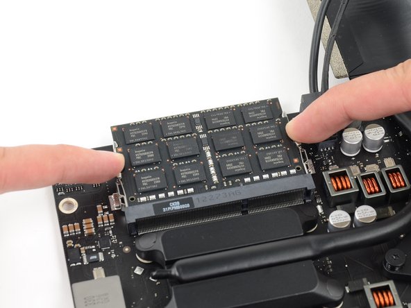
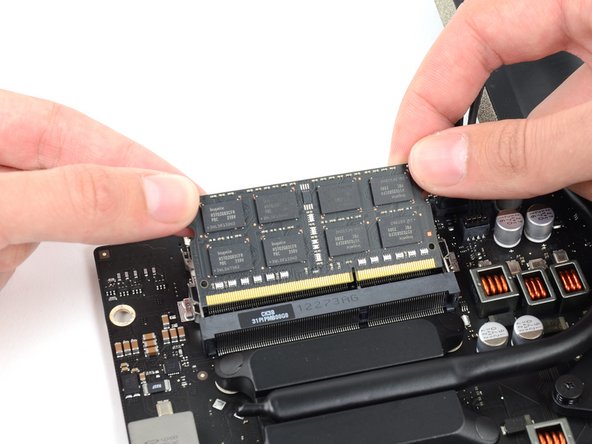
    • Release the tabs on each side of the RAM module by simultaneously pushing each tab away.

    • The RAM module should pop up slightly from its socket.

    • Grab the top left and right corners of the RAM module and carefully pull it straight out of its socket.

    • Repeat the process to remove additional RAM modules as necessary.

  63. Этот шаг не переведен. Помогите перевести

    : шаг 63, изображение 1 из 3 : шаг 63, изображение 2 из 3 : шаг 63, изображение 3 из 3
    • Disconnect and remove the SATA data and power cables from the logic board.

  64. Этот шаг не переведен. Помогите перевести

    : шаг 64, изображение 1 из 1
    • Remove the four 12 mm T10 shoulder screws from the spring plate behind the CPU.

  65. Этот шаг не переведен. Помогите перевести

    : шаг 65, изображение 1 из 1
    • Remove the spring plate from behind the CPU heat sink.

  66. Этот шаг не переведен. Помогите перевести

    : шаг 66, изображение 1 из 1
    • Lift and remove the backing plate from behind the CPU heat sink.

    • The backing plate has two posts that fit into alignment holes in the logic board and heat sink.

  67. Этот шаг не переведен. Помогите перевести

    : шаг 67, изображение 1 из 2 : шаг 67, изображение 2 из 2
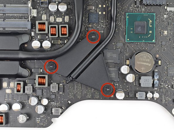
    • Remove the three 12 mm T8 Torx screws securing the GPU heat sink to the logic board.

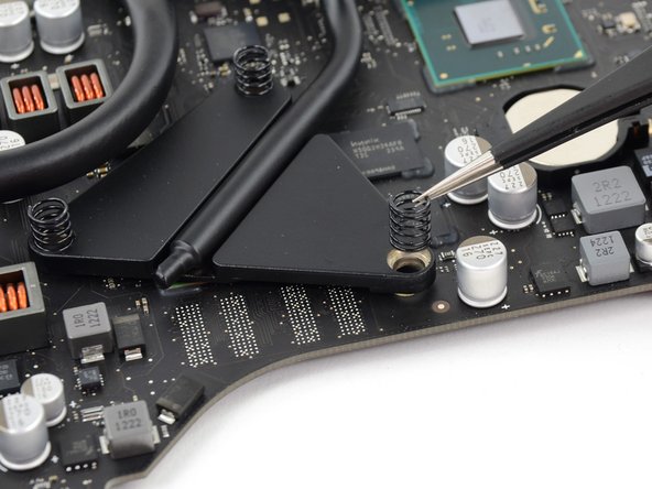
    • Remove the three springs left behind.

    • These springs might come up with the screws; be careful not to lose track of them.

  68. Этот шаг не переведен. Помогите перевести

    : шаг 68, изображение 1 из 2 : шаг 68, изображение 2 из 2
    • Lift and remove the heat sink up off the logic board.

    • The CPU will most likely detach with the heat sink, so be careful about where you lay it down.

  69. Этот шаг не переведен. Помогите перевести

    : шаг 69, изображение 1 из 2 : шаг 69, изображение 2 из 2
    • The CPU will most likely be stuck to the heat sink with thermal compound.

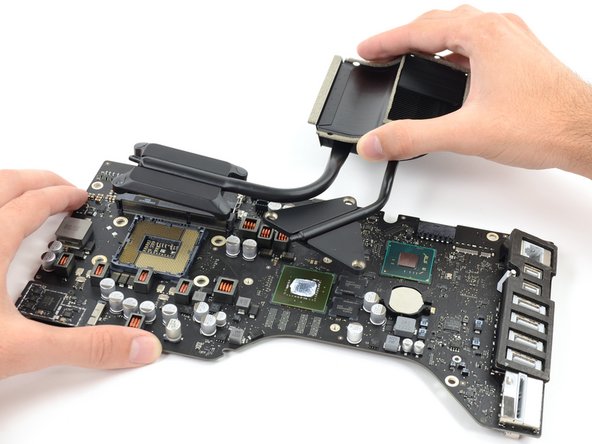
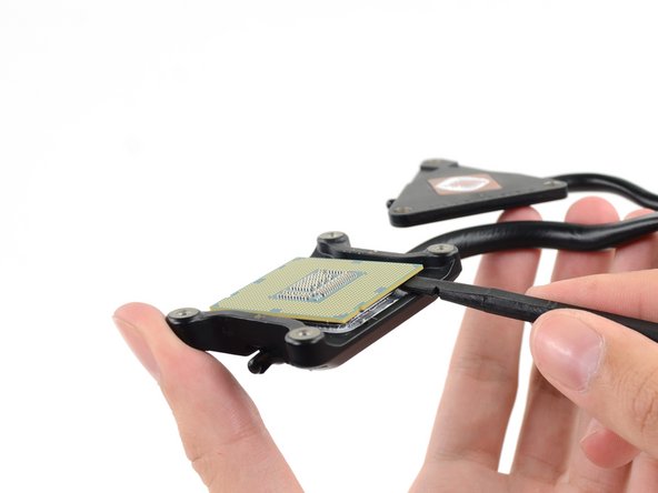
    • Insert the flat edge of a spudger between the CPU and heat sink.

    • Gently pry the CPU off the heat sink by slightly twisting the spudger upwards.

  70. Этот шаг не переведен. Помогите перевести

    : шаг 70, изображение 1 из 1
    • Remove the CPU from the heat sink. Be careful not to touch the contacts.

    • To install a new CPU, see our thermal paste guide for instructions on cleaning and preparing the thermal surfaces and applying a new layer of thermal compound onto the CPU and GPU dies.

Финишная черта

36 участников успешно повторили данное руководство.

Sam Goldheart

Участник с: 10/18/12

465 656 Репутация

Автор 538 руководств

Команда

iFixit Участник iFixit

Staff

135 членов

Автор 16 732 руководств

10 Комментариев

I just upgraded my 2544 base model iMac (2.7 i5, 8gb ram, 5400 rpm HDD) with all possible options: 3.1 i7 3770s CPU, 16gb ram and a Samsung EVO 850 SSD. The upgrades all worked perfectly, and were made possible for an amateur such as myself thanks to these amazingly detailed and well photographed instruction guides. I can't tell you how helpful they were to me, and just wanted to thank you and share my success. I am an amateur with no significant experience at all with computers, so I wanted to encourage anyone who is hesitant to get the right tools for the job and get to it! Thanks again!

dtfreelancevideo - Ответить

What are the compatible CPUs? Is the 3770s the highest option or is it possible to upgrade to an even faster CPU used in 27in models?

Thanks.

s m - Ответить

The i7-3770s is the max. for the 21,5" 2012 late iMac, because of the thermal design.

Thanks iFixit for providing this excellent guide!

opeter1 - Ответить

Hello,

thank you for this great guide.

which other CPU could I use to upgrade from 2,7 Ghz i5 CPU?

Is an i7-3770 also possible or will he get too hot? (I am asking, because I cannot find any i7-3770s for under 300€)

thank you

robert - Ответить

Use Core i7-3770 3.4Ghz (70€ eBay ) (not 3770s) + HyperX Impact  16Gb 1833Mhz 70€ + SSD Samsung 1TB QVO (trim enable) 95€ - all good, without issue. Same TDP have i7 - 3770K iMAC 2012 now have same power as basic iMac 2019. I’m happy. https://browser.geekbench.com/v4/cpu/130...

Vadim Rotari - Ответить

Добавить комментарий

Просмотр статистики:

За последние 24часов: 5

За последние 7 дней: 36

За последние 30 дней: 162

За всё время: 19,384