Этот документ имеет более свежие изменения. Перейти к последней непроверенной версии.
Введение
This guide details removing the logic board in a 2017 iMac 4K in order to upgrade the RAM and the SATA hard drive (for example, if you purchased the Max Your Mac kit).
Some images in this guide were taken from the 2015 model, which has some small visual differences.
If you are replacing/upgrading your hard drive, be sure to clone your existing hard drive onto the replacement drive prior to performing this upgrade to keep your files and operating system in place.
This guide is marked "potentially dangerous" because it requires you to handle a power supply that contains large capacitors. Unplug the iMac and hold the power button down for at least 10 seconds to help discharge the capacitors. Handle the board by the edges and do not touch surface components.
Выберете то, что вам нужно
-
-
Before beginning any work on your iMac: Unplug the computer and press and hold the power button for ten seconds to discharge the power supply's capacitors.
-
-
-
Starting on the left of the display, near the power button, insert the iMac Opening Tool into the gap between the glass panel and the rear enclosure.
-
-
-
Use the tool like a pizza cutter—roll it along through the gap, and it will cut the foam adhesive through the center.
-
Run the tool up along the left side of the display.
-
-
-
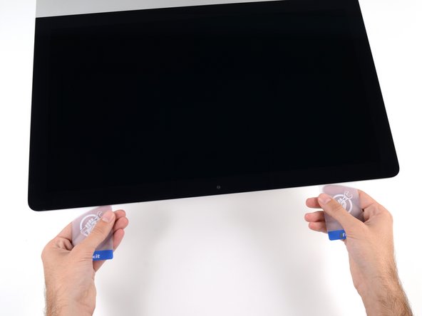
Starting from the top right corner of the iMac, wedge a plastic card between the display and frame.
-
-
-
Gently twist the plastic card sideways to create a gap between the display and frame.
-
Move slowly and be careful not to stress the display glass too much—you only need to make a gap of about 1/4".
-
-
-
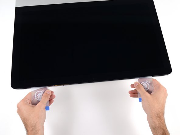
Slide the card toward the center of the display to cut any of the remaining adhesive along the top right corner of the iMac.
-
-
-
Wedge the plastic card into the top right corner once again, and leave it there to prevent the adhesive from resticking.
-
-
-
Insert a second plastic card into the gap between the display and frame near the top left corner of the iMac.
-
-
-
Gently twist the card upward, slightly increasing the space between the display and frame.
-
-
-
Slide the plastic card toward the center, again stopping just before the iSight camera.
-
-
-
With both plastic cards inserted as shown near the corners, gently twist the cards sideways to increase the gap between display and case.
-
Begin to lift the top of the display up from the frame.
-
-
-
Hold the display with one hand while using your other hand to unplug the display power cable.
-
-
-
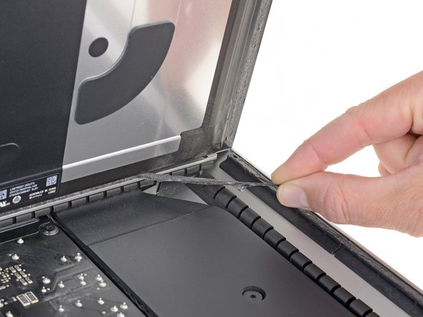
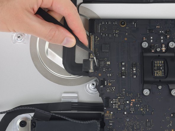
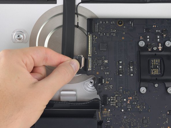
Continuing to support the display with one hand, flip up the metal retaining bracket on the display data cable.
-
Carefully pull the display data cable from its socket on the logic board.
-
-
-
Grasp the small tab at the end of one of the bottom edge display adhesive strips and pull the adhesive toward the top of the iMac to remove it.
-
Repeat this step with the other adhesive strip and remove it.
-
-
-
-
Lift the display up from the frame and remove it from the iMac.
-
It may be necessary to slowly lift from one side to peel against the remaining adhesive.
-
-
-
Remove the following five Phillips screws holding the lower support bracket in place:
-
Four 3.2 mm screws
-
One 1.7 mm screw
-
-
-
Remove the lower support bracket (a.k.a. "chin strap") from the iMac enclosure.
-
-
-
Remove the following T10 Torx screws securing the hard drive brackets to the iMac:
-
Two 21 mm screws
-
One 9 mm screw
-
One 27 mm screw
-
-
-
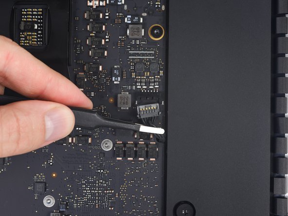
Use the tip of a spudger to push each side of the power button cable connector and gently walk it out of its socket.
-
-
-
Use the tip of a spudger to push each side of the power supply control cable connector and gently walk it out of its socket.
-
-
-
Remove the two 7.2 mm T10 Torx screws securing the power supply to the rear enclosure.
-
-
-
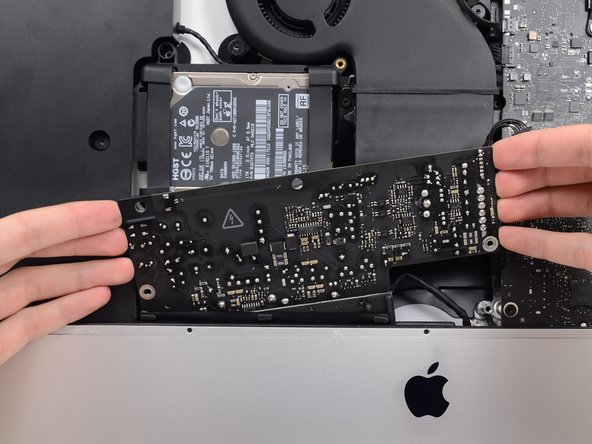
Pull the power supply slightly up and out from the rear enclosure.
-
Rotate the power supply counterclockwise, lifting the right side up about an inch higher than the left.
-
-
-
Slide the power supply to the right to clear the screw posts on the rear enclosure.
-
-
-
Rock the power supply forward and remove it from its recess in the rear enclosure.
-
-
-
Squeeze the tab on the back side of the DC power cable connector and pull it straight out of its socket on the back of the logic board.
-
-
-
Use the flat end of a spudger to press the clip on the side of the AC inlet cable connector inward.
-
While pressing on the release clip with the spudger, grasp the AC inlet cable, and pull the connector straight out of its socket.
-
-
-
Gently pull the fan cable connector straight away from its socket on the logic board.
-
-
-
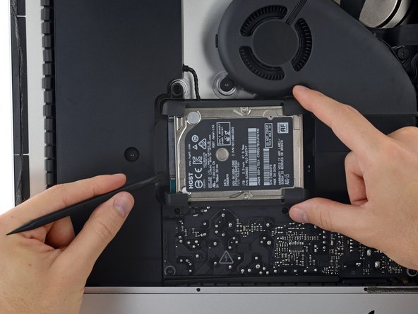
Lift the hard drive from the edge nearest the logic board and pull it slightly out of its recess.
-
-
-
Use a spudger to disconnect the single SATA cable by prying it gently away from the hard drive.
-
Remove the hard drive assembly from the iMac.
-
-
-
Peel the rubber bumper off one side of the hard drive.
-
Repeat for the other side.
-
-
-
Remove the 7.3 mm T8 Torx screw securing the hard drive tray to the rear enclosure.
-
-
-
Gently pull the right speaker cable connector straight down and out of its socket on the logic board.
-
-
-
Gently pull the left speaker cable straight out of its socket on the logic board.
-
-
-
De-route the left speaker cable by pulling it straight up out of the retaining clip in the back of the rear enclosure.
-
-
-
Similarly to the previous step, de-route the SATA and power cables by pulling the braid straight up out of the retaining clip.
-
-
-
Peel up the piece of tape connecting the left speaker connector to the SATA power and data cables.
-
-
-
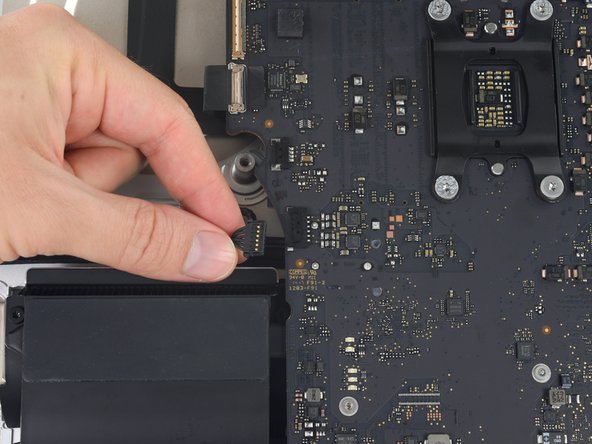
Flip up the metal retaining bracket on the FaceTime camera cable connector.
-
Pull the FaceTime camera cable straight out of its socket on the logic board.
-
-
-
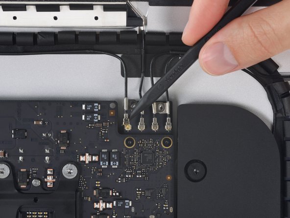
Remove the two 4.0 mm T5 Torx screws securing the four antenna connectors to the AirPort/Bluetooth card.
-
-
-
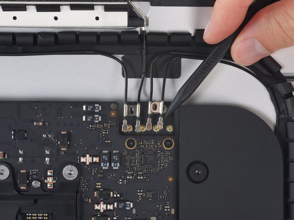
Disconnect all four antenna connectors by prying them straight up from their sockets on the AirPort/Bluetooth card.
-
-
-
Use the flat edge of a spudger to pry the headphone jack cable connector from its socket on the logic board.
-
Push the cable up and out of the way of the logic board.
-
-
-
Remove the following T8 Torx screws securing the exhaust duct to the rear enclosure:
-
Two 6.2 mm screws
-
Two 4.7 mm screws
-
-
-
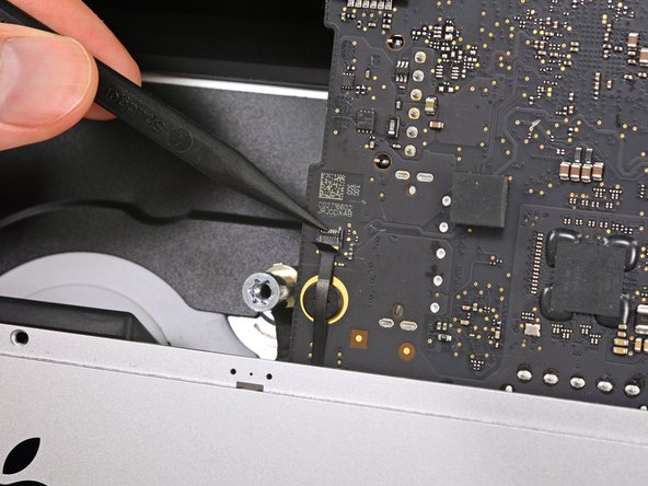
Flip the latch on the microphone ZIF connector and pull the cable out of its socket on the logic board.
-
-
-
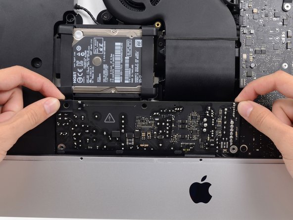
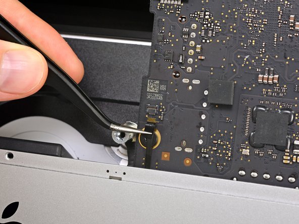
Remove the four 7.3 mm T8 Torx screws securing the logic board to the rear enclosure.
-
-
-
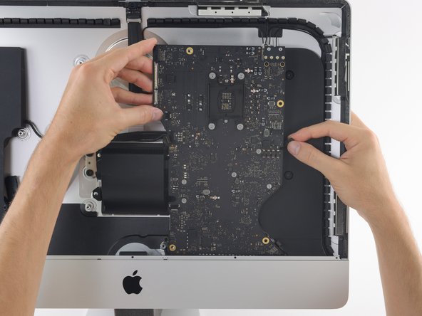
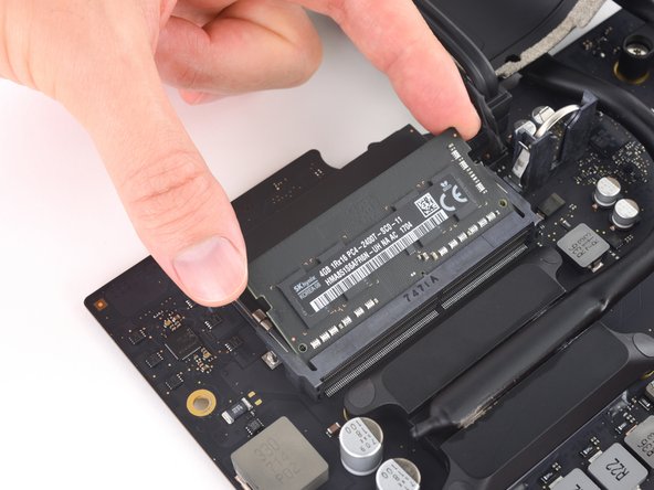
Handling the board by the edges, flip the logic board over to access the two RAM modules.
-
-
-
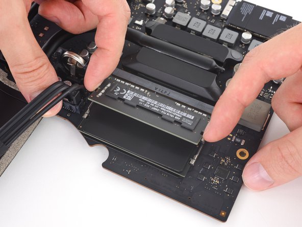
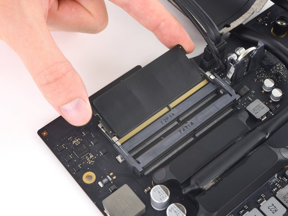
Two clips secure the RAM module in place, one on each side. Using your fingers, spread the clips away from the RAM module.
-
-
-
Peel off and transfer the thermal pad from the original RAM stick to your replacement RAM before you install it in the lower slot.
-


To reassemble your device, follow these instructions in reverse order.
To reassemble your device, follow these instructions in reverse order.
Отменить: Я не выполнил это руководство.
22 участников успешно повторили данное руководство.


5 Комментариев
Be very careful. I also replaced my fusion drive with a 2T SSD and maxed the ram to 32gb but somehow I screwed up the microphone. I had to pay Apple 520.00 to fix it because they had to replace the whole back cover. Took about a week to get it back from Apple. Good luck!
Frank, along the bottom right hand side of the aluminum case where the screen slots in there are three small holes. Make sure the adhesive doesn't cover those as it is the microphone. To do this, I laid the screen adhesive, and then cut a section out over those holes.
successful upgrade my iMac to 2 TB SSD and 32gb RAM with no complications. Thank for this useful guide
Hats off team!! Really nice and helpful guide.
Done and worked on an iMac Retina 4K 2017. Upgraded SSD Crucial 2Tb MX500 + 2 x 16Gb RAM. Finished and working!!
100% satisfied with the improvement.
Please take your time and read ALL users comments. They have experienced issues that you can avoid. Use adhesive tape to fix some connectors, be careful when removing the display and check everyting works before setting the new adhesives.
Time 1h 47m. Most time consuming and delicated parts - Removing screen and adhesive and finally setting the new adhesives and fitting the screen.