Перейти к основному содержанию

Эта версия возможно содержит некорректные исправления. Переключить на последнюю проверенную версию.

Абсолютно необходимое руководство
Это руководство предназначено только для использования в качестве обязательного условия для других руководств. Оно не полностью само по себе.

Выберете то, что вам нужно

  1. Этот шаг не переведен. Помогите перевести

    : шаг 1, изображение 1 из 2 : шаг 1, изображение 2 из 2
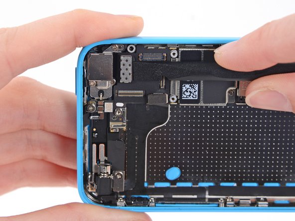
    • Use the flat end of a spudger to disconnect the audio control cable connector from its socket on the logic board.

    • Disconnect the rear facing camera cable connector from its socket on the logic board.

  2. Этот шаг не переведен. Помогите перевести

    : шаг 2, изображение 1 из 1
    • A small piece of tape may obscure the logic board grounding clip. If so, use a pair of tweezers to remove the tape.

  3. Этот шаг не переведен. Помогите перевести

    : шаг 3, изображение 1 из 2 : шаг 3, изображение 2 из 2
    • Remove the following screws securing the logic board grounding clip to the rear case:

    • 1.2 mm Phillips #000 in the top side-wall

    • 2.5 mm Phillips #000

  4. Этот шаг не переведен. Помогите перевести

    : шаг 4, изображение 1 из 1
    • Use tweezers to remove the logic board grounding clip.

  5. Этот шаг не переведен. Помогите перевести

    : шаг 5, изображение 1 из 1
    Инструмент, используемый на этом этапе:
    Standoff Screwdriver for iPhones
    $5.49
    Купить
    • Remove the following screws securing the logic board to the rear case:

    • Two 2.3 mm Phillips screws

    • Three 2.7 mm standoff screws

    • Standoff screws are best removed using a standoff screwdriver or bit.

    • In a pinch, a small flathead screwdriver will do the job—but use extra caution to ensure it doesn't slip and damage surrounding components.

  6. Этот шаг не переведен. Помогите перевести

    : шаг 6, изображение 1 из 3 : шаг 6, изображение 2 из 3 : шаг 6, изображение 3 из 3
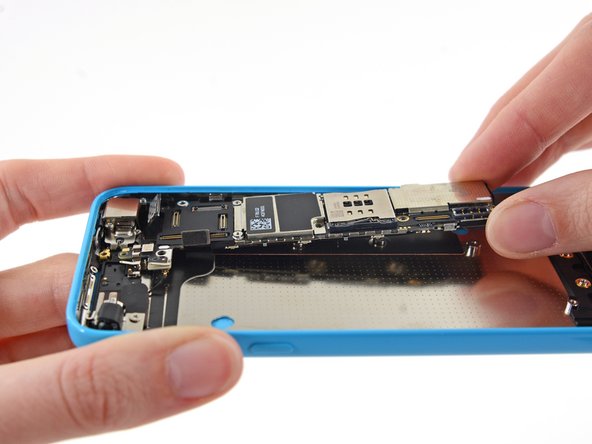
    • Holding the phone level, lift the bottom end of the logic board up enough to grasp it with your fingers.

    • Pull the logic board away from the rear-facing camera just enough to expose the gold contact cap under the top end of the board.

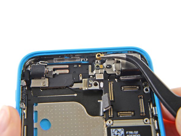
    • Remove the gold-colored contact cap from the threaded post in the rear case, and set it aside.

  7. Этот шаг не переведен. Помогите перевести

    : шаг 7, изображение 1 из 2 : шаг 7, изображение 2 из 2
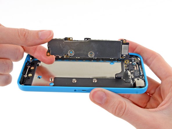
    • Flip the logic board up toward the volume control buttons to expose the antenna connector.

    • Do not try to remove the logic board from the rear case yet, as it is still connected by an antenna cable on the back.

  8. Этот шаг не переведен. Помогите перевести

    : шаг 8, изображение 1 из 1
    • Disconnect the antenna connector from the back of the logic board.

  9. Этот шаг не переведен. Помогите перевести

    : шаг 9, изображение 1 из 1
    • Remove the logic board from the rear case.

Финишная черта

Andrew Optimus Goldheart

Участник с: 10/17/09

502 846 Репутация

Автор 407 руководств

Команда

iFixit Участник iFixit

Staff

135 членов

Автор 16 817 руководств

0 Комментариев

Добавить комментарий

Просмотр статистики:

За последние 24часов: 0

За последние 7 дней: 0

За последние 30 дней: 0

За всё время: 224