Перейти к основному содержанию

Reemplazo del condensador del Acer AL1716

Английский
Испанский
Шаг 3
Acer AL1716 Capacitor Replacement: шаг 0, изображение 1 из 3 Acer AL1716 Capacitor Replacement: шаг 0, изображение 2 из 3 Acer AL1716 Capacitor Replacement: шаг 0, изображение 3 из 3
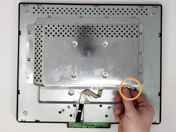
  • Remove the two 0.7 mm Phillips #0 screws on the sides of the centerpiece motherboard cover.

  • Remove by hand the two hexagonal screws securing the digital visual interface (DVI) input.

  • The DVI is typically a blue/black connector with two built-in screw connections on either side. It is secured by hand tightening the two side screws.

  • Push the centerpiece motherboard cover toward the body to remove.

Retira los dos tornillos Phillips #0 de 0,7 mm a los lados de la cubierta de la placa base de la pieza central.

Retira con la mano los dos tornillos hexagonales que sujetan la entrada de la interfaz visual digital (DVI).

El DVI suele ser un conector azul/negro con dos conexiones de tornillo integradas en cada lado. Se asegura apretando a mano los dos tornillos laterales.

Empuja la cubierta de la placa base de la pieza central hacia el cuerpo para quitarla.

Ваш вклад лицензируется под свободной лицензией Creative Commons .