Введение
L7580 is a great multifunction printer from HP. Here we will discover what's inside the printer and take apart it's sensors and DC motors.
Выберете то, что вам нужно
-
-
Remove the 3 T8 Torx screws from the paper feeder.
-
Lift the white surface to reveal the two notches.
-
Push the notches to detach the paper feeder mechanism.
-
-
-
After removing the paper feeder, you will notice the slotted opto switch.
-
Remove the back cover to demount cable jacks.
-
Pull and detach the paper feeder mechanism.
-
-
-
Remove the T8 Torx screws from the right cover.
-
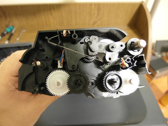
You will see the feeder's mechanics after removing the cover.
-
Remove the top cover, and here is the first DC motor and its encoder.
-
-
-
Pull the scanner cover up to detach it from the main body. Then, remove the T8 Torx screws around the scanner window.
-
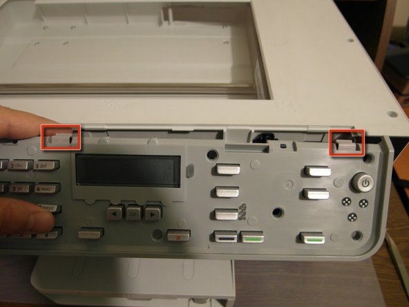
Remove the control panel by pulling it.
-
Finally, remove the inner layer of the control panel by forcing the notches.
-
-
-
Remove the flat cable from the control panel.
-
Remove the T8 Torx screws to see what's inside the control panel.
-
Then, we will see the 4 layers of the control panel.
-
-
-
Remove the two T8 screws to detach the scanner cover.
-
Lift the cover up to reveal scanner mechanism.
-
And we have our second DC motor and encoder. Plus, a carrier mechanism.
-
-
-
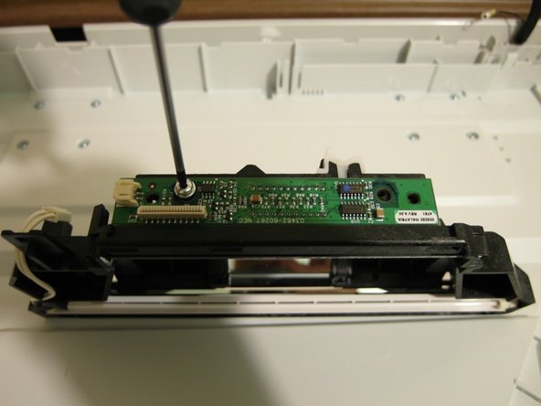
Remove the scan head's top cover by pressing the two notches on the back.
-
Remove the T8 screws of the circuit board.
-
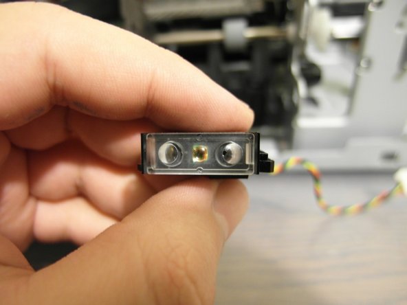
Here is the scanner sensor and the objective.
-
-
-
-
Remove all the screws from the back, including the ones inside the 3 covers.
-
Remove the two screws from the top of cartridge change cover.
-
Detach the two side covers by pulling them.
-
-
-
Detach the back cover.
-
Remove the 4 screws from the both hinges.
-
Then, remove the scanner cover to reveal printing mechanism.
-
-
-
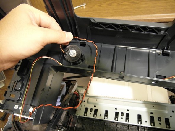
Remove the screws of the cover.
-
You will notice the speaker below the cover.
-
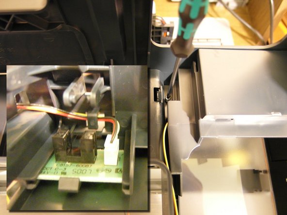
Remove the screws of cartridge door. There is another slotted opto switch here.
-
-
-
There is an extra weight block on the print mechanism to prevent vibration.
-
Remove the red marked screw to detach ink hose.
-
Remove the green marked screw to detach ink cartridge slot.
-
Finally, we have the ink hose and the nozzles.
-
-
-
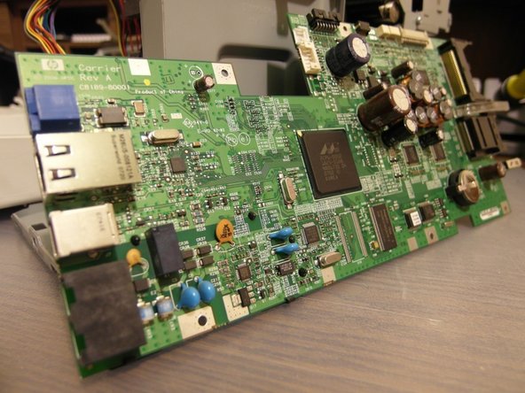
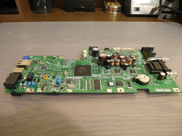
Remove the screws to detach the mainboard of the printer.
-
The board has a power input, an Ethernet connector, a USB device port, phone line input and outputs, memory card slots, a USB host port, various internal connectors and a CR2032 RTC battery.
-
-
-
Rotate the printer right to reach the other DC motor.
-
Remove the two screws connecting the motor to the body.
-
We will have another DC Motor.
-
-
-
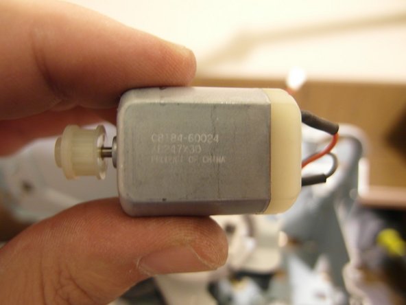
L7580 has a lot of DC motors inside. Detach the ink cartridge slots by removing the screws to discover another DC one.
-
-
-
This is the ink cartridge pumping mechanism. The last DC motor we detached controls this mechanism.
-
The opto switch reports the mechanism's position.
-
Communication between the board and cartridges is being established by serial data line as I guess.
-
-
-
Then, we see here the print head cleaning mechanism.
-
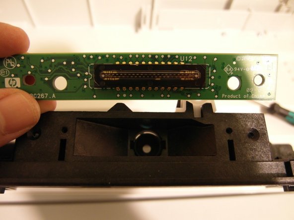
The master print head (which includes two removable heads) has a circuit board inside.
-
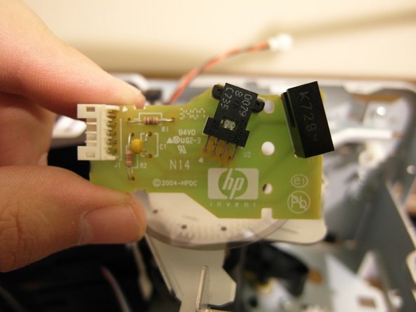
And this is the paper type detector. It has been compacted a bit when comparing to previous versions.
-
-
-
Reaching to the bottom layer, this is the paper feeding mechanism.
-
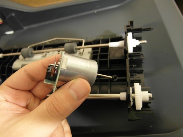
By removing the top cover, we discover the sixth and the last DC motor with an encoder.
-
-
-
At the final step, we are discovering an air pump for the print head cleaning mechanism. It's surprising!
-


8 Комментариев
If you only need to remove the scanner window and don't want to go through the hassle of dissembling the ADF:
1. Remove the seven T8 screws around the scanner window and the two behind the control panel.
2. Lift up on the front of the window assembly to loosen it
3. Close the scanner cover/ADF.
4. Lift the scanner window assembly from the front up and back, being careful of the cable running to the ADF at the back right
If you try to open the window assembly with the cover/ADF open, it will bind at the back as the hinge is a single piece that's difficult to take apart.
Hi Eric
Nice teardown. I have been hoping to find a diagram to see how the gear systems interact. My unit picks paper and pushes it to the rear rollers but the rollers are not turning. They spin freely and I think that is odd unless there is a clutch or a broken gear. Hence my looking for a diagram. Do you know how these rollers are fed? Do they have their own motor??
Thanks for any comment
Sal -
Sal what did you learn about the rear rollers spinning freely. I have the exact same situation, but the pick and feed roller on the front of the printer work but the paper doesn’t feed on the back side of the printer. This causes a jam and ultimately a out of paper error. I was hoping to be able to feed paper through manually but it gets stopped on the back side, I’m thinking its a feed roller not spinning or being spun. Did you find a diagram?