This does look fixable, but it'll take a little detective work. See, the thing is, you need that black wire to connect up to whatever it was originally connected to. Normally that pad gives you the spot to solder it to, but it doesn't have to be the only place.
Those copper traces are covered up by a layer of what's called solder mask, which is an insulator to keep things from shorting out. You've ripped part of that trace off the board along with the pad (the path traced by the line from the solder pad almost to that plus mark (+) printed on the board) , but there's obviously more that we can't see yet.
What I would do would be to take an X-Acto knife and carefully scrape away the top layer of solder mask at the end of that ripped off trace, right around the plus sign. You should be able to free up more of that trace to the point where you'll have a spot big enough to solder the wire onto. There's no reason that shouldn't work just fine; that'll get the electrical signal going back to where it was originally headed.
Alternatively, it looks like that trace probably heads on over to one or more of those vias to the right of the plus sign. The via is a hole in the board that's plated all the way through and allows the signals to move from one layer of the board to a different layer. Normally there's no solder mask in those, so if you can identify the one the trace was headed for, you can simply stick the wire down into that hole and hit it with a drop of solder and that should provide a mechanically and electrically stable connection.
Of course, the problem is in identifying which hole it's going to. If you can scrape off a little solder mask at the end of the broken trace, then you could use an ohmmeter or continuity tester to locate which via it's going to. Otherwise, use a bright light on the other side of the board to see if you can follow where the trace goes.
Hopefully that'll give you some ideas, but basically it's my opinion that you should be able to fix that pretty easily.
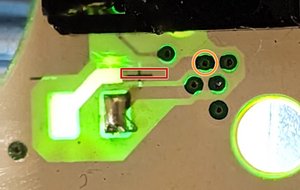
Okay, your picture is great; it shows us exactly where the trace goes to.
You have two choices; you can either scrape off some of the solder mask and solder the wire to the exposed copper in the area I've outlined in red, or you can solder it to the via I circled in orange. Either way should restore the original electrical path. Of course, that assumes the diameter of the wire is small enough to fit into the hole in the board provided by the via; if it's too big you'll want to scrape the trace and do it that way instead.
Был ли этот ответ полезен?
Проголосовали
Отменить
Оценка
2
Отмена
Scroll through this thread to find the appropriate place for this comment. Then, click "Attach comment to this post" to move it.