Tom, I just checked on cross referencing the shaver and it comes back from type 5705 to model 6520, 6525,6550 and 6515 flex integral ultra. Braun does not show me a 5705model, but type 5705. So your 5705 is actually a 6000 series :) anyhow, batteries for that model are available at places like this. It is soldered unto the logic board.
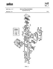
Pos. No. Part Description Part Number
1 Protective cap 5503074
2 5000 series shaving foil frame order by description
3 5000 series cutter block order by description
4 Swivel frame (black) 5505633
4 Swivel frame (silver) 5504630
5 Sealing plate 5503014
6 Bearing screw 5504046
7 Screw 5504099
8 Head carrier (black) 5505634
8 Head carrier (silver) 5504631
9 Lower frame 5505032
10 Chassis with no. 11, 12, 15, 16 5504639
11 Locking pin 5504087
12 Spring 5504200
13 Lever 5504089
14 Spring 5504090
15 Latch 5504926
16 Switch 5504962
17 Motor 5704627
18 PCB, cpl. 5505631
19 Cover, cpl. 5504638
20 Hood 5504112
21 Sliding plate; w/no. 22 to 25 5705636
22 Lever 5504093
23 Leg spring 5504095
24 Leg spring 5504092
25 Transmission lever 5504091
26 Light insert 5505043
27 Cord socket, cpl. 5505638
28 Housing case; with no. 29 (black) 5705632
28 Housing case; with no. 29 (silver) 5704628
29 Locking button 5705012
30 End cap (dark gray) 5705637
30 End cap (silver) 5705640
31 Screw 5586038
32 Plug pin (gray) 5704055
Cleaning brush 5503120
Coiled cord 5323015
Case 5504852
To disassemble it, follow the service manual :
"The dismantling procedure is described in a logical order. For individual repairs, the order of the description can be altered.
· Shaving foil frame (2) - to be unlocked by pushing button "A";
- to be removed.
· Cutter block (3) - to be removed.
· Swivel frame (4) - Unscrew bearing screws (6).
- Remove swivel frame (4).
· Plug pins (32) - to be taken off with a needle.
· End cap (30) - unscrew screws (31).
- remove end cap (30).
· Housing case (28) - unlock locking button (29).
- take off housing case (28).
· Head carrier (8) - unscrew screws (7).
- remove head carrier (8).
· Lower frame (9) - to be removed by prying open with a knife between head
carrier (8) and lower frame (9).
· Cover (19) - to be taken off by unhinging the 4 notches "B" on the sides.
· PCB (18) - to be held underneath the batteries.
- to be taken out off the chassis (10).
· Motor (17) - Motor lower side to be unhinged out of plastic holder "C".
- Motor axis to be pushed out of oscillating bridge.
· Cord socket (27) - to be removed by snapping out notch "D" in the chassis (10).
· Light insert (26) - to be pushed out of the chassis (10); to be removed.
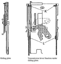
· Hood (20) - to be taken off the leading pins on the left and right sides of the sliding plate (21).
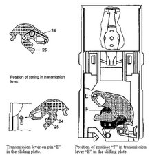
· Sliding plate (21) - to be pulled upwards out of the chassis (10), when switch is in position" 2". (Care has to be taken that the leg spring (24) and transmission lever (25) do not slip away.)
Reassembly
The reassembly has to be performed in reversed order. However, attention has to be paid to the following points:
Sliding plate (21) - Before inserting the sliding plate (21) please ensure that the transmission lever (25) and leg spring (24) are assembled correctly. (If necessary, attach transmission lever (25) with leg spring (24) to pin "E" of the sliding plate, while positioning cam "F" of the lever (22) in the switching coulisse, as shown in diagram).