Введение
It is a design flaw to connect a nylon gear on a splined shaft. the nylon will eventually strip, (Thank you Mrs. Fiorina for telling your engineers to do it cheap.) The goal of this procedure is to show you how to get to the gear and secure it to the shaft.
Выберете то, что вам нужно
-
-
Review this utube video You won't be doing all of that, but it's a good place to start.
-
Remove the ink cartridges, the duplexer/paper-jam-access-cover and the paper tray.
-
Remove lower side covers.
-
This is done by prying out the edge of of the cover that is next to the paper tray and pushing the edge out.
-
Once this face is out, push the cover back.
-
-
-
Remove 2x 15mm pop off right cover.
-
Split the part on the front and back, then the top. Pry up the top and tilt the top of the panel open, then pull the cover up and out.
-
-
-
Remove two 10mm screws.
-
Lift and pull out right cover
-
Note the left cover is plugged into the motherboard. Lift front, pull out.
-
lift off paper tray cover
-
-
-
Be gentle.
-
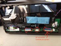
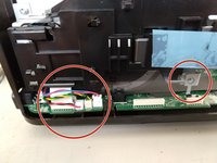
IMPORTANT, one has ZIF (zero-insertion -force) connector. Lift up the bar and then remove the cable. During reassembly, ensure the bar is up, insert the cable and push the bar down.
-
The cables go through ferrite collars. Leave the collars in place, but be sure to put the cables back through the collars during reassembly.
-
carefully move the cables to the back
-
-
-
-
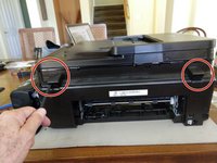
Pop off two covers in the back.
-
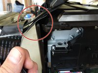
Unsnap the hinges. This is tricky. Gently push the top assembly up. This will create a small gap between the hinge and the top. Slide a thin prying tool into the gap and pull gently down to release the hinge.
-
Once unsnapped, pull the top assembly away from the hinges. (You did carefully move the cables to the back before this step, right?)
-
-
-
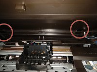
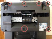
Remove 6x 15mm screws
-
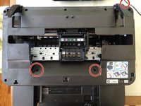
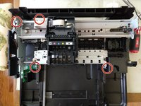
remove 3x 10mm screws, the third one is on the back.
-
disconnect the red/blue cable from the motherboard on the side and unhook from guides.
-
lift off top
-
Remove right side
-
-
-
Disconnect the front panel from the motherboard
-
Remove 2x 15mm screws.
-
Lift out front panel
-
-
-
Remove 4x 15mm screws
-
Remove 1x machine screw and disconnect remaining cables..
-
Disconnect linkage
-
-
-
A lot of tubing needs to stay connected. If it comes loose, it's really messy and hard to do.
-
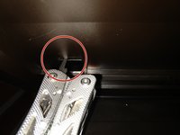
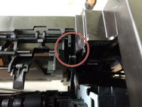
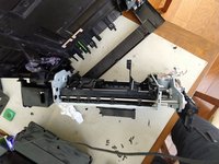
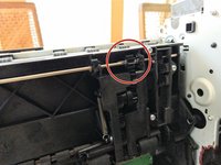
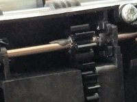
Position the printer like the picture shows.
-
The second and third pictures show the location of the problem. I had tried the non-disassembly procedure, but it failed for me. You can see a glob of JB Weld.
-
-
-
OK, I got you here. I'm going to try to:
-
clean off all the JB Weld
-
Slide the gear over
-
put a couple of drops of Superglue on the splines, push the gear back over the splines and let cure while I eat a sandwich
-
Mix up some JB Weld and ensure that I get it 360 degrees and both sides. Wish me luck!
-
-
-
It's not much fun getting that printer engine back on. Put on you latex gloves.
-
Before you start, though, clean up those pinch wheels that grab the paper. alcohol, let dry, sandpaper them a little.
-
IMPORTANT: Get rotary-pulse encoder, the then clear plastic disk, needs to be clean and go into that "slot" (which is an opto-coupler, that counts the pulses.
-


The fact that you are here trying to fix this printer is a testament that, ultimately, it was the greed of the top level management that requires this fix.
Yeah, I had a really hard and messy time getting the print engine back in place. The epoxy hasn’t cured yet, so I don’t know if I fixed it or bricked it.
Отменить: Я не выполнил это руководство.
12 человек успешно провели ремонт по этому руководству.
16 Комментариев
Can this be fixed by cutting a hole in the bottom of the printer???
Yes
The disassembly is not necessary. Using a soldering iron with a knife tip, I cut an access opening in the bottom of the printer. There is a long oblong (looks like)well directly beneath the stripped gear in the bottom panel of the printer. I cut the opening under there, the flat oblong feature on the bottom. Don't cut the structural reinforcing features.
Using a stiff wire, the superglue gel was applied to splines. The shaft can be rotated in one direction. Slide the gear over an let it harden, then carefully dab the gear sides only. Let it cure.
Total time under 45 minutes.
Really difficult to fix.
But I didn't want to buy a new printer because of this little bug.
I'd rather fix things than keep buying new ones.
It’s been a long time since I did this. The super glue and JB weld failed shortly. In subsequent attempts I bricked it.
Kevin, I like your thinking, but one would run the risk of causing more damage to the device.
Achim, I hear ya! Just this morning, for the second time, I super glued the lid to my teapot. Alas there is a lot of greed in this world. I bought a new printer and, it, too, is a crappy design (paper tray hangs up when I pull it out to put in more paper). Look into helping out at a RepairCafe/Restarters/FixitClinic event.
How I did this in 5 minutes: removed the paper, taped a small mirror on the paper tray bottom, turned the printer upside down, and dropped superglue drops on the spline, using the mirror to position. I added a few drops on the side of the repositioned gear but that might not be nessessary.
NOTE: make sure the due-ink-reservoir (underneath the parked cartridges location) is emptied with a cloth before turning the printer!