Введение
Solder bridges are an inevitable occurrence during the soldering process. This guide will show you how to fix a solder bridge and test your circuit after the fix.
A solder bridge can lead to serious damage to your device in the form of a short. A short is when too much current passes through a component, which can lead to device failure. This guide shows how to prevent a particularly dangerous short by clearing a solder bridge between the power and ground rails on a circuit board.
This guide involves the use of high temperatures when desoldering and soldering connections, so take appropriate precautions when the soldering iron is operating. You may need to repeat steps as necessary due to the nature of the desoldering and soldering process.
If you are new to soldering and desoldering, review the How to Solder and Desolder Connections guide.
Выберете то, что вам нужно
-
-
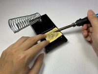
Set the soldering iron to 300 °C (575 °F) and wait for the iron to heat up to the desired temperature.
-
-
-
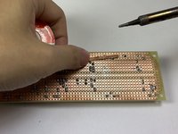
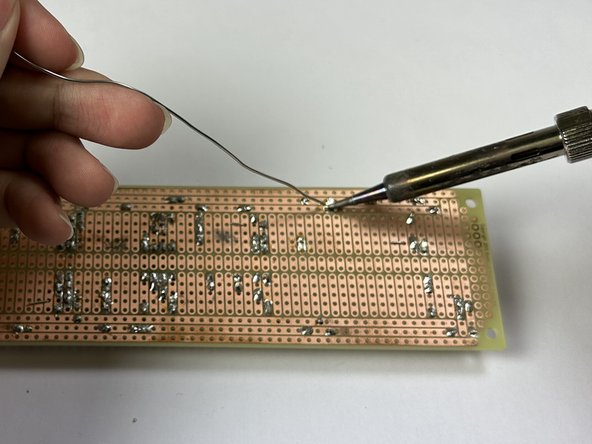
Locate the solder bridge on the circuit board.
-
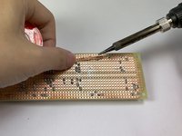
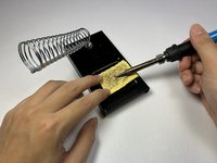
Apply the solder wick to the affected area.
-
-
Инструмент, используемый на этом этапе:Tweezers$4.99
-
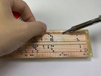
With the solder wick on top of the solder bridge, heat the wick using the soldering iron by pressing on top of the affected area.
-
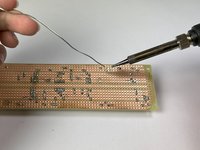
Continue to apply pressure with the soldering iron to the solder bridge until the solder is melted and absorbed by the wick.
-
-
-
-
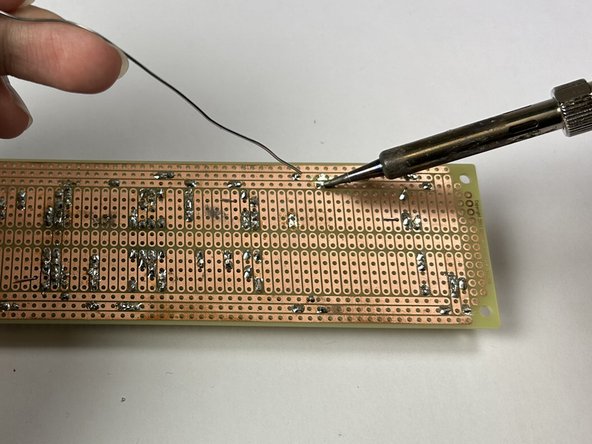
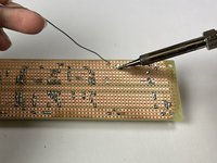
Apply the soldering iron to the contact point.
-
Once the contact point is hot, reapply the solder to the contact point.
-
Continue applying the solder to the contact point until the pin is solidly attached and the rails are separate from each other.
-
-
-
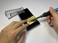
Hold down the damp sponge.
-
While the soldering iron is hot, use a rubbing motion across the sponge to remove excess solder off the soldering iron tip.
-
When you have cleaned the iron, melt a small amount of solder on it to "re-tin" the tip.
-
-
-
Connect the red (positive) probe to the Voltage and Resistance Socket.
-
Connect the black (negative) probe to the Common/Ground Socket.
-
Set the multimeter knob for continuity testing. This is typically labeled with diode/audio symbols.
-
-
-
Connect the black probe to the circuit board rail where one end of the solder bridge was.
-
Connect the red probe to the circuit board rail where the other end of the solder bridge was.
-
If the fix is successful, the multimeter should read "OL" on the screen, indicating an open circuit. There should be no beep, which means the rails are no longer connected.
-


To reassemble your device, follow these instructions in reverse order.
Отменить: Я не выполнил это руководство.
19 человек успешно провели ремонт по этому руководству.

Команда

UC Davis, Team 2-5, Morris Spring 2023 Участник UC Davis, Team 2-5, Morris Spring 2023
UCD-MORRIS-S23S2G5
3 членов
Автор 9 руководств