Введение
If your Logitech G27 will not respond properly, even after calibrating, you may need to replace its optical encoder. The optical encoder is a small electronic device that turns the wheel's rotation into an electronic signal for the computer to understand. It isn't too hard to replace, you just need plenty of patience because you'll be taking out a lot of screws! Make sure your wheel is completely unplugged before starting this replacement.
Выберете то, что вам нужно
-
-
Remove the six gray 25mm hex screws with a 4mm allen wrench.
-
Carefully lift up the wheel, but do not disconnect it from the rest of the device.
 Спросите у FixBot
-
-
-
Carefully lift the wheel off of the hub, exposing the 2 shifter paddle wires and PCB board.
-
-
-
Remove the two 7.5 mm silver screws holding the green PCB board in the wheel with a Phillips #1 screwdriver.
-
-
-
Carefully pinch and unplug the large 7-pin connector under the PCB board.
-
-
-
You can now fully remove the wheel from the hub. Set it aside until you put the wheel back together.
-
Remove the innermost three 37.5mm silver screws with a Phillips #2 screwdriver.
-
Remove the wheel hub and push the connector through the center of the hub.
-
-
-
The wheel hub can now be set aside and flip over the steering wheel housing to reveal the under side.
-
Remove the eight 15.9mm silver surrounding screws underneath the wheel housing with a Phillips #1 screwdriver.
-
-
-
-
Rotate the housing back over and remove the top half of the housing revealing the majority of the components of the wheel.
-
The housing cover can be set aside until you put the wheel back together.
-
-
-
Remove the four 7.3mm silver screws attaching the green PCB board to the motor housing with a Phillips #2 screwdriver.
-
-
-
Unplug the three plastic connectors on the left side of the PCB board.
-
Unplug the two plastic connectors on the top of the PCB board.
-
Unplug the three plastic connectors on the right side of the PCB board.
-
-
-
Remove the PCB board after all of the plastic connectors are disconnected.
-
You can now set it aside.
-
-
-
Remove the two 12.3mm upper black screws with a Phillips #2 screwdriver.
-
Remove the two 15.5mm bottom silver screws with a Phillips #1 screwdriver.
-
-
-
Remove the PCB board mount and remove the clear plastic piece underneath.
-
Set them aside until you reassemble the wheel.
-
-
-
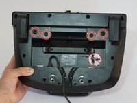
After following the prerequisite guide, invert your device.
-
Remove the four center-most screws from the bottom of the device with a Phillips #1 screwdriver.
-
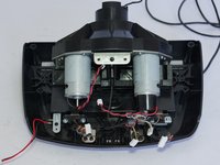
Invert your device back to its original position, and completely remove the motor housing from the rest of the device.
-
-
-
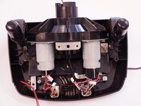
Remove the eight screws attaching the metal motor housing to the plastic with a Phillips #1 screwdriver.
-
Completely remove the motor housing from the plastic.
-
-
-
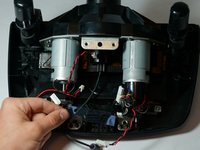
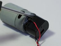
Turn the device around, and remove the three screws attaching the left most motor to the metal backing using a Phillips #1 screwdriver.
-
Completely remove the motor from the metal backing. This will make it easier to move around when replacing the optical encoder.
-
-
-
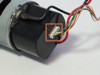
Remove the white 5-pin adapter from the end of the optical encoder.
-
Remove the plastic casing by prying it off with a screwdriver or a plastic opening tool.
-
-
-
Remove the two silver screws from the underside of the optical encoder with a Phillips #0 screwdriver, and the circuit will be free from the motor and ready to replace!
-
-
-
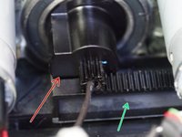
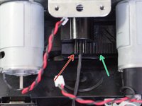
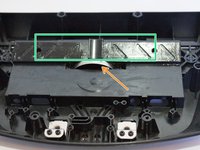
During reinstallation make sure when doing this step to align the stop on the wheel gear with the track as shown in the second and third pictures.
-
Also make sure that the metal half-circle clip is placed properly inside the slot.
-
After placing the metal clip in the slot, place the plastic cog on top of the clip and on the rail.
-


To reassemble your device, follow these instructions in reverse order.
Отменить: Я не выполнил это руководство.
52 человек успешно провели ремонт по этому руководству.
Команда

Cal Poly, Team 15-4, Amido Spring 2015 Участник Cal Poly, Team 15-4, Amido Spring 2015
CPSU-AMIDO-S15S15G4
4 членов
Автор 25 руководств
35 Комментарии к руководству
Where can you get the encoder to replace it?
If your wheel doesn't calibrate.Then check your optical encoder. It's 90 percent of the issue You can find replacement in the ETSY with the buyer name " abrapartabra " for logitech optical encoder 30 or 60 slot they have for Logitech G25 , G27 and DFGT . They have been made like original, but with more reliable plastic. We fixed our Logitech steering wheel
Hello and thanks for the guide. I understand this might be off topic, but would you happen to know the pinout of the7-pin connector in step 5? There is no label on the pins. Thanks in advance for your time.
Very much appreciate your assistance & time putting this together. I Chose the expoxy route. My wheel IS BACK!
Are you sure about Step 19 alignment. Some other guy with G25 says it has to be dead centre alligned otherwise you get blinking lights.And that's exactly what happens to me.