Введение
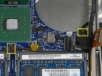
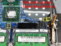
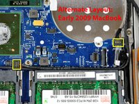
This motherboard includes all ports on the left side.
Выберете то, что вам нужно
-
-
Use a coin or spudger to rotate the battery-locking screw 90 degrees clockwise.
-
-
-
Unscrew the three evenly-spaced Phillips 000 screws from along the rear wall of the battery compartment.
-
-
-
Grasp the right end of the L-shaped memory cover, then pull it towards you so it clears the battery compartment opening.
-
Lift the memory cover up and out of the computer.
-
-
-
Remove the following 3 screws:
-
One 11 mm Phillips#00 in the middle of the lower case. (Head: 5mm dia. x .75mm thick)
-
Two 14.5 mm Phillips #00 (Head: 5mm dia. x .75mm thick)
-
-
-
Remove the following 3 screws from the rear wall of the battery compartment:
-
One 3 mm Phillips #0. (Head: 2.75 mm. dia.)
-
Two 4 mm Phillips #0 on the either side. (Head: 2.75mm dia.)
-
-
-
Remove the two Phillips screws from either side of the right wall of the battery compartment (not the ones closest to the battery connector).
-
Two 6.25 mm Phillips #000. (Head: 4 mm. dia. x .5mm thick)
-
-
-
Remove the four indicated Phillips screws from the front wall of the battery compartment. When working from the left, remove the 2nd, 4th, 7th and 9th screws.
-
Four 3.25 mm Phillips #000. (Head: 4 mm. dia. x 4mm thick)
-
-
-
Remove the following 4 screws from the back of the computer:
-
Two 11 mm Phillips #00, with Shank (2.2mm dia. x 2 mm len.) (Head: 3.2 mm. dia. x .5mm thick)
-
Two 7.25 mm Phillips #00, with Shank (2mm dia. x 3.75 mm len.) (Head: 3.2 mm. dia. x .5mm thick)
-
-
-
Remove the two Phillips screws from the optical drive (right) side of the computer:
-
Two 5.2 mm Phillips #00, with shank (2.3mm dia. x 3.25 mm len.) (Head: 3.2 mm. dia. x .5mm thick)
-
-
Инструмент, используемый на этом этапе:Plastic Cards$2.99
-
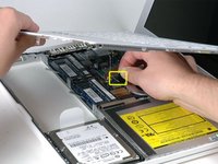
Use a plastic opening tool, an expired plastic credit, or a similarly-thick card to pry up on the upper case, starting in the upper-left corner and working around to the front of the computer.
-
-
-
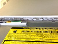
While holding up the upper case, pull up the black tab on the connector end of the silver ribbon cable away from the connector's socket on the logic board.
-
-
-
Disconnect the MagSafe board cable from the logic board by pulling the snap-in connector out (to the right).
-
-
-
-
Remove the single 9 mm Phillips screw securing the left speaker to the lower case.
-
Lift the left speaker out of its housing and set it to the side.
-
-
-
Remove the following 3 screws:
-
Two 7.5 mm Phillips from either end of the left I/O frame.
-
One 9 mm Phillips from the middle of the left I/O frame.
-
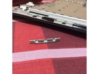
Remove the small black plastic spacer at the bottom of the left I/O frame.
-
-
-
Lift the left I/O frame up and out of the computer. Pay attention to the thin metal EMI fingers, as they may catch as you remove the left I/O frame.
-
-
-
Use a spudger to move the gray display data and black speaker cables to the right. This will reveal a silver screw securing the fan housing to the lower case.
-
-
-
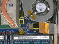
Disconnect the black fan connector and two temperature sensor connectors from the logic board by pulling/prying them directly up.
-
-
-
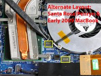
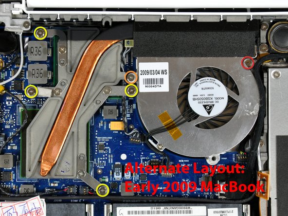
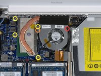
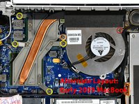
Remove the following 6 screws:
-
One 3 mm Phillips on the right side of the fan.
-
One 6 mm Phillips on the left side of the fan.
-
Four 9 mm Phillips securing the heat sink to the lower case.
-
-
-
Hold the heat sink with one hand and the fan with your other hand, and lift the heat sink and fan assembly out of the computer. The fan is attached to the heat sink only with a strip of black felt tape, so be sure to remove both parts as a unit.
-
-
-
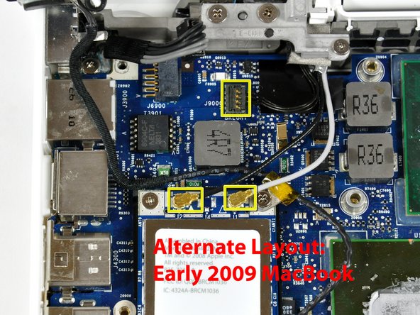
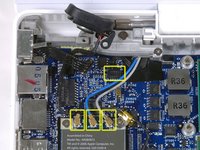
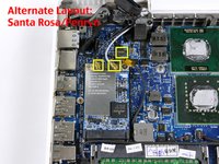
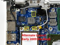
Disconnect the three antenna cables from the Airport card, and the black inverter cable from the logic board.
-
-
-
Remove the following 2 screws from the Airport card:
-
One 3 mm Phillips from the left side.
-
One 8 mm (with a large 2 mm head) Phillips from the right side.
-
-
-
Grasp the Airport card at its top and slide it toward the screen and out of the computer.
-
-
-
Use a spudger to disconnect the left speaker connector from the logic board.
-
Lift the left speaker out of the computer.
-
-
-
Disconnect the display data cable by pulling up on the black plastic pull-tab. If there is no pull-tab on the top of the connector, it may be helpful to use a spudger to disconnect this connector.
-
-
-
Use a spudger to disconnect the speaker connector and bluetooth connector from the logic board.
-
-
-
Use a spudger to carefully disconnect the microphone cable from the logic board. You'll want to work from side to side, and slowly wiggle the connector out of its socket.
-
-
-
Deroute the microphone cable from the silver metal clip just above the right RAM slot.
-
-
-
Use a spudger to carefully pry the battery connector up and disconnect it from the logic board.
-
-
-
Remove the three 3 mm Phillips screws securing the logic board to the lower case.
-
-
-
Lift the logic board up from the right side, and slide it up and out of the computer.
-
-
-
Turn the logic board over.
-
Peel the PRAM battery up from its location on the logic board, removing tape as necessary.
-
-
-
Disconnect the PRAM battery cable from the logic board and remove the PRAM battery from the computer.
-
-
-
Pull back on the metal lever and slide the RAM chip out of the logic board.
-
Repeat this process for the other RAM chip if there are two RAM chips currently installed in your computer.
-


To reassemble your device, follow these instructions in reverse order.
Отменить: Я не выполнил это руководство.
176 человек успешно провели ремонт по этому руководству.

12 Комментарии к руководству
Thanks so much for this guide! My mac wouldn't turn on after spilling some wine on it a few days before. After I followed these steps and let the parts lay out to dry overnight (after cleaning everything with rubbing alcohol), I put it back together and it turned on!! Thank you a million times!
The shop wanted over $700 ($600 for parts, $90+ for labor) to fix it, which I definitely wasn't going to pay, so I decided to fix it myself. I spent right at $150 for a new logic board, magsafe board, and RAM upgrades and delved into the depths of the Macbook. I followed every step of the guide closely and she started right up after reassembly. Great guide, thanks!
Great Guide - i used zip-lock bags for screws and wrote the step numbers on each.
I've managed to replace a macbook 1,1 logic board with a macbook 2,1 (2GHz) one, and replaced a 4,1 on another machine (which looks interchangeable with older ones)
It is NOT possible to replace these older boards with a newer macbook 5.2 board because ALL the connectors are different, and the screw-holes are in different places.
Managed to revive my years old dead Macbook! Glad I found this guide and helped me diagnose and fix the problem. (Only wish I would have found this BEFORE I started disassembling my Macbook. Half the beginning screws don't have a home now. Whoops) Overall great guide. The alternate pictures were great since they were more in-line with mine. Easy to follow, and everything turned out great. Thanks!