Эта версия возможно содержит некорректные исправления. Переключить на последнюю проверенную версию.
Выберете то, что вам нужно
-
-
Выкрутите 10 выделенных шурупов:
-
Три 14.4 mm Phillips #00 шурупа
-
Три 3.5 mm Phillips #00 шурупа
-
Четыре 3.5 mm Phillips #00 шурупа с бортиками
-
-
Этот шаг не переведен. Помогите перевести
-
Use your fingers to pry the lower case away from the body of the MacBook near the vent.
-
Remove the lower case.
-
-
Этот шаг не переведен. Помогите перевести
-
Use the edge of a spudger to pry the battery connector upwards from its socket on the logic board.
-
-
Этот шаг не переведен. Помогите перевести
-
Bend the battery cable slightly away from its socket on the logic board so it does not accidentally connect itself while you work.
-
-
Этот шаг не переведен. Помогите перевести
-
Use the flat end of a spudger to pry the AirPort/Bluetooth ribbon cable connector up from its socket on the logic board.
-
-
Этот шаг не переведен. Помогите перевести
-
Carefully pull the camera cable out of its socket on the logic board.
-
-
Этот шаг не переведен. Помогите перевести
-
Carefully move the AirPort/Bluetooth ribbon cable out of the way as you peel the camera cable off the adhesive securing it to the subwoofer and the AirPort/Bluetooth bracket.
-
De-route the camera cable out from under the retaining finger molded into the AirPort/Bluetooth bracket.
-
-
-
Этот шаг не переведен. Помогите перевести
-
Use the tip of a spudger to pry the antenna connector closest to the logic board up from its socket on the AirPort/Bluetooth board.
-
De-route the antenna cable from under the finger molded into the AirPort/Bluetooth bracket.
-
-
Этот шаг не переведен. Помогите перевести
-
Using the method described in the last step, disconnect the remaining three antenna connectors.
-
De-route their cables from the slots cut in the AirPort/Bluetooth bracket.
-
-
Этот шаг не переведен. Помогите перевести
-
Remove the following five screws:
-
Two 10.3 mm Phillips screws
-
Two 3.1 mm Phillips screws
-
One 5 mm Phillips screw
-
-
Этот шаг не переведен. Помогите перевести
-
Pull the AirPort/Bluetooth assembly and the Subwoofer upward near the center of the side of the optical drive until they clear each other.
-
-
Этот шаг не переведен. Помогите перевести
-
Remove the AirPort/Bluetooth assembly, minding the fragile antenna contact near the corner of the upper case.
-
-
Этот шаг не переведен. Помогите перевести
-
Remove two of the three 6 mm T8 Torx screws securing the right side of the display to the upper case.
-
-
Этот шаг не переведен. Помогите перевести
-
Grab the plastic pull tab secured to the display data cable lock and rotate it toward the DC-In side of the computer.
-
Pull the display data cable straight out of its socket on the logic board.
-
-
Этот шаг не переведен. Помогите перевести
-
Remove the following two screws:
-
One 8.6 mm Phillips screw
-
One 5.5 mm Phillips screw
-
Remove the display data cable retainer from the upper case.
-
-
Этот шаг не переведен. Помогите перевести
-
Remove the piece of foam tape covering the display screws near the MagSafe DC-In board.
-
-
Этот шаг не переведен. Помогите перевести
-
Remove two of the three 6 mm T8 Torx screws securing the left side of the display to the upper case.
-
-
Этот шаг не переведен. Помогите перевести
-
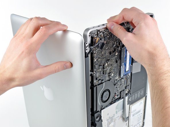
Open your MacBook Pro so the display is perpendicular to the upper case.
-
Place your opened MacBook Pro on a table as pictured.
-
While holding the display and upper case together with your left hand, remove the remaining T8 Torx screw from the lower display bracket.
-
-
Этот шаг не переведен. Помогите перевести
-
Remove the last remaining T8 Torx screw securing the display to the upper case.
-
-
Этот шаг не переведен. Помогите перевести
-
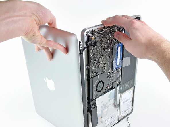
Grab the upper case with your right hand and rotate it slightly toward the top of the display so the upper display bracket clears the edge of the upper case.
-
Rotate the display slightly away from the upper case.
-
Lift the display up and away from the upper case, minding any brackets or cables that may get caught.
-


Отменить: Я не выполнил это руководство.
84 участников успешно повторили данное руководство.

8 Комментариев
Step 18 and 19 is easier if you place the bottom keyboard down, with the display hanging over the edge of a table. This stabilizes the bottom assembly, making teardown and reassembly easier for one person
Fantastic tip - I placed it in front of me so the display rested on my thighs while the base was flat on the table - very safe, no fear of dropping/slipping.
Annette -
Thank you Phillip for providing this Guide. I used it to replace a bad LCD assembly after a water spill damaged it. The last Step 20 is very difficult. I had the worst time trying to separate the two parts after I removed the final Torex screw. It took a while, trying different angles, but I finally got it. Putting in the new one was a trivial exercise...
Phillip, thank you so much for this excellent guide. I have no technical background at all but I found it very easy to use - and it saved me hundreds of dollars on a professional repair job. Keep up the good work!
Thank you so much for going to the effort to explain the steps. It worked out perfect. I work as a Lean Engineer developing Standard Work, which is exactly what you have done. I couldnt have done it any better. Thank you if you ever come to Ireland I owe you a pint :)