Введение
Use this guide to replace just the LCD rather than the entire display assembly.
Выберете то, что вам нужно
-
-
Use your fingers to push both battery release tabs away from the battery and lift the battery out of the computer.
-
-
-
Remove the four identical Phillips 3.4 mm screws from the memory door. These screws have 4 mm diameter heads rather than the 3 mm heads on the body screws.
-
-
-
Lift the memory door up enough to get a grip on it, and slide it toward you, pulling it away from the casing.
-
-
-
Remove the three Phillips screws in the battery compartment near the latch. Apple was nice enough to tilt these screws at a slight angle to make them easier to remove. On the A1261 these screws have 4 mm diameter heads rather than the 3 mm heads on the body screws.
To Damon - possibly the thread on the bottom of the upper case is obstructed.
I found that I needed to fight the latch magnet with the right-most screw in the photo. The screw was pulled away from the hole so a magnetized screwdriver was not enough to place it. I needed tweezers to hold the screw in place until it bit.
No, these screws won’t bite going back in — struggled for an hour. Lost hope of success.
Case screw holes perfectly lined-up, neatly closed body, screw threads/head are fine (Apple quality screws), perfect screwdriver.
The left one is in, other two simply will not bite whatsoever. Slightly irritating eventually turned to madly infuriating. I have a similar, earlier model and that was smooth to replace these exact, slightly angled screws (so I have experience).
Q: Are the centre and right-hand screws absolutely essential — or can I give up and leave them out?
(By the time you read this, that’s what I’ll have done)(out of sheer frustration)
-
-
-
Remove the following six screws:
-
Two 14.5 mm T6 Torx screws on either side of the RAM slot.
-
Four 3.4 mm Phillips screws along the hinge.
These instructions are actually wrong. The 14.5 mm screws are for along the hinge, the 2 on either side of the RAM slot are about 10 mm.
-
-
-
Remove the four 3.4 mm Phillips screws on the port side of the computer.
When reassembling, please be careful not to screw into the wrong spot. I accidentally screwed into the DVI port and it was hard to remove the screw after that. I had to disassemble the whole thing again, only to find that I couldn't remove the screw from within as it was encased. After much scraping and prodding with a sewing needle, I was able to get that screw out. Phew!
-
-
-
Rotate the computer 90 degrees again and remove the four Phillips screws from the side of the computer.
-
-
-
Lift up the back of the case and work your fingers along the sides, freeing the case as you go. Once you have freed the sides, you may need to rock the case up and down to free the front of the upper case.
Be very careful not to bend the screw tabs on the top case the perimeter screws attach to. Bending them causes them to quickly fatigue and potentially break off. When reassembling the top case, be sure the tabs are all *inside* the case before reseating it. If you get resistance, pull the case back up, check the tabs and reseat the top case again.
-
-
-
Disconnect the trackpad and keyboard ribbon cable from the logic board.
-
Remove the upper case.
Disconnecting this cable is optional, if instead you tip up the top case ~75 degrees, propping it up with something non-metalic (wedged in or by the battery compartment). Unplugging a connector from the main circuit board always carries slight additional risk.
It's not really necessary to disconnect the trackboard/keyboard ribbon cable. You can simply lean the upper case against the LCD.
After having successfully removed/reattached the ribbon cable several times while trying to revive this computer for back-up use the securing/release tabs on the connector broke. The connector then will not hold the cable properly and connecting fails. Tried various methods of propping the cable in the connector to get full contact but eventually all efforts failed, too. Result: essentially a dead motherboard as no replacement for the connector seems available. Sadly, not worth the extra effort to try further repairs.
-
-
-
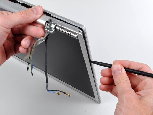
Disconnect the two antenna cables from the AirPort Extreme card, the iSight and inverter cables from the left side of the logic board, and the display data cable from the right side of the logic board. Be careful to slide the connectors as they may become damaged otherwise.
-
Carefully peel the iSight and inverter cables off the top of the left fan and de-route the AirPort antenna cables from the channel in the left speaker.
anybody got any advice re: how to detach the connector on that tiny little ribbon, the one on the upper left with the larger ribbon/connector alongside it? I tried and tried... gave up for fear of damaging the wires, plus concern about how difficult it might be to get it back in. Thx in adv
Firenzeitalia: The tiny little black one is the scariest part of the whole job. You need to use a firm spudger to slide it out to the left. Possibly even use the pointy end, but it slides out quite easily.
The hard part is getting it to slide back in again later — especially if you have large fingers. Essentially, you’re going to have to do it blind — and by ‘feel’ — because you can’t see what you’re doing.
Fortunately, Apple made it so that the black housing lines-up to the sides and the four tiny receptor prongs: once you’ve slid it into place and it looks correctly in, you then push down on it — to snap it in properly.
This is the time to re-attach the keyboard (put a cloth over the screen), plug in power and turn the machine on to test you’ve done it right.
If you’ve attached the tiny Inverter housing correctly, the screen will light up and boot as expected. If the screen remains black, remove the keyboard and cable again — gently — and check the Inverter and Display Data Cable are correctly inserted.
-
-
-
Remove the ten silver T6 Torx screws securing the display (five on each side-take note that the inside screws on both sides are longer with a thinner head).
To clarify the placement of the different screws:
There are two sets of 2 on each side and two sets of 3 on the insides. The "long" screws with "flat" heads are meant for the INSIDE of the sets of 3. I will represent short screws by the letter "S" and the long screws by the letter "L":
S S - S S L - L S S - S S
But what are the measurements of the screws? Its T6 but how many millimeters long is the screw?
The longer two (middle) screws are about 14mm and the rest (identical) are approximately 10mm.
-
-
-
-
Grasp the display assembly on both sides and lift it up and out of the computer.
If you came to the Display Removal guide to replace just the LCD panel and not the entire assembly, you need to head over to the Front Bezel replacement guide.
-
-
-
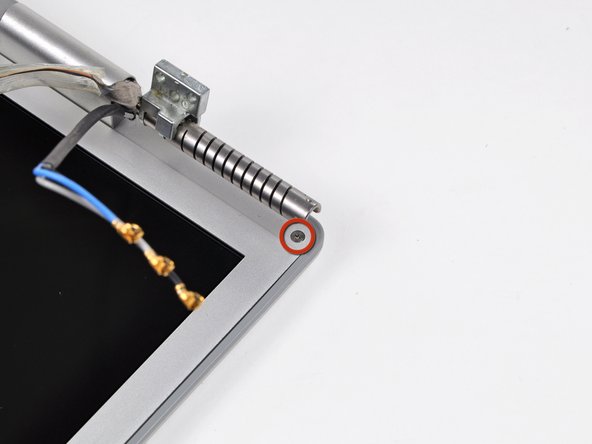
Remove the Phillips screws from the lower left and right corners of the display (two screws total).
-
-
-
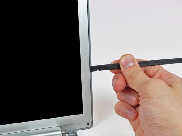
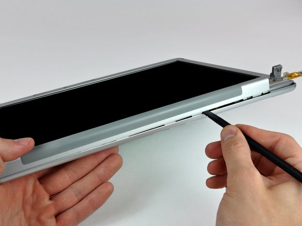
Insert the flat end of a spudger perpendicular to the face of the display between the plastic strip attached to the rear bezel and the front bezel.
-
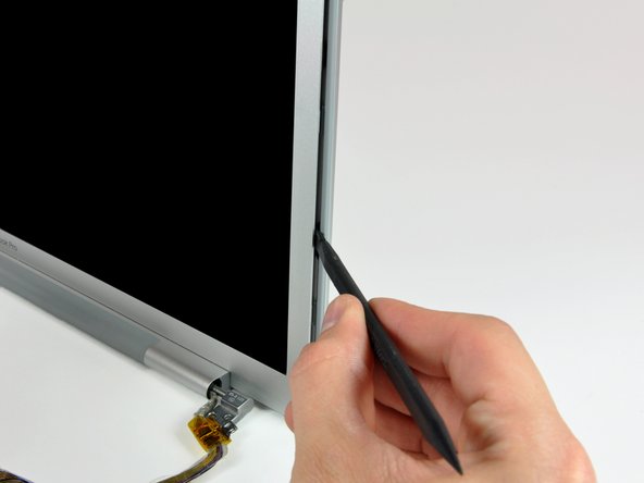
With the spudger still inserted, rotate it away from the display to separate the front and rear bezels.
-
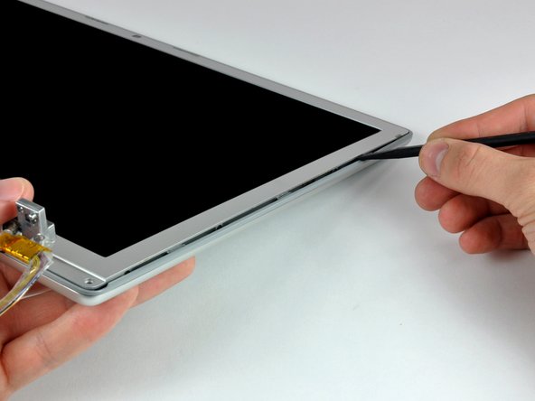
Work along the right edge of the display until the rear bezel is evenly separated from the front bezel.
-
-
-
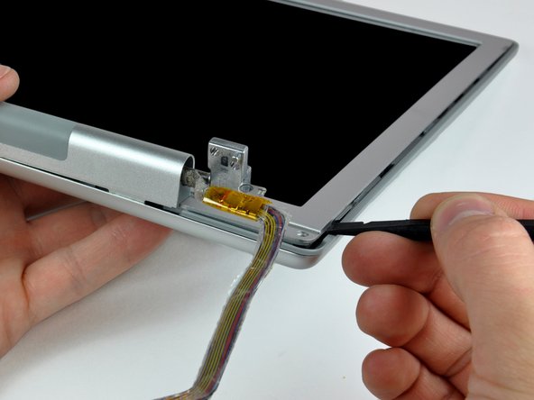
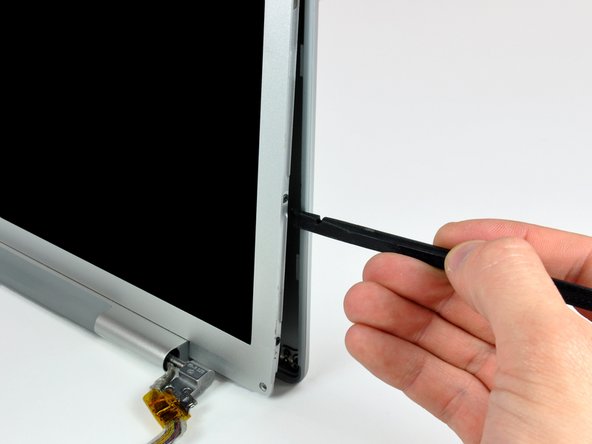
Insert your spudger between the front and rear display bezels at the lower right corner of the display.
-
Pry the rear bezel away from the front bezel to slightly separate the bottom edge of the rear display bezel.
-
-
-
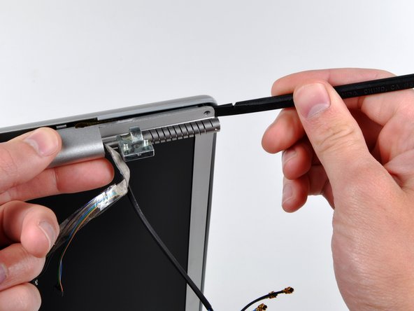
Insert the flat end of a spudger into the gap between the rear display bezel and the clutch cover.
-
Twist the spudger to separate the lower edge of the rear display bezel from the clutch cover.
-
Work along the lower edge of the rear bezel until it is evenly separated from the clutch cover.
-
-
-
Now that the right and bottom edges of the rear bezel are slightly separated from the front bezel, use a spudger to pop the rear bezel off the tabs near the lower right corner of the display.
Prying the rear display bezel off up with the plastic spudger can be frustrating. The plastic spudger just can't provide the torque. I actually used the combination of the plastic spudger (to start the separation) and a metal spudger to provide sufficient force to separate. I wrapped the metal spudger with some tape to prevent scratching. As usual, care is required to not bend the front bezel.
-
-
-
Insert the flat end of a spudger between the front bezel and the plastic strip attached to the rear bezel near the screw holes at the bottom corners of the display.
-
Rotate your spudger toward the rear bezel to separate it from the front bezel.
-
-
-
Slightly lift the lower edge of the display and pull it away from the rear display bezel.
-
The rear display bezel remains.
-
-
-
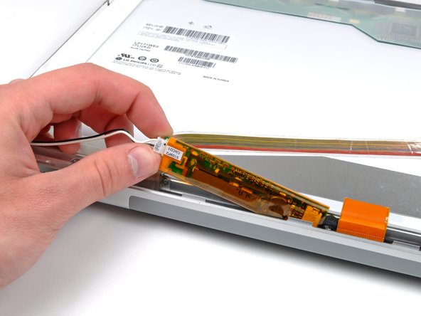
Remove the strip of tape covering the backlight leads.
-
Carefully lift the inverter out of the clutch cover enough to reach the backlight connector.
-
-
-
Remove the several strips of tape securing the ribbon cables to the LCD.
-
-
-
Use the flat end of a spudger to carefully peel the three antenna strips off the lower edge of the LCD.
-
-
-
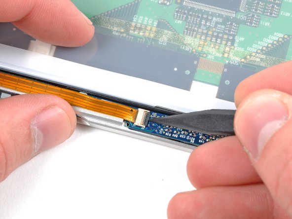
Use the tip of a spudger or your fingernail to flip up the ZIF retaining flap on the camera cable socket at the edge of the camera board near the top center of the front display bezel.
-
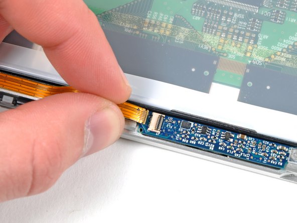
Pull the camera cable out of its socket.
-
Peel the camera cable off the foam tape along the top edge of the display.
-
-
-
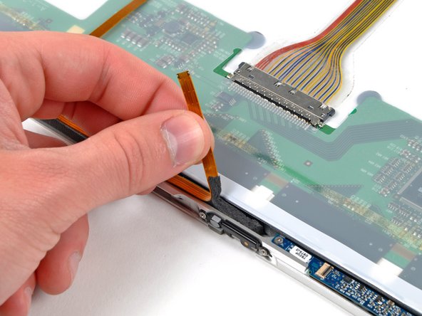
Pull the display data cable toward the bottom edge of the display to disconnect it from the LCD.
-
-
-
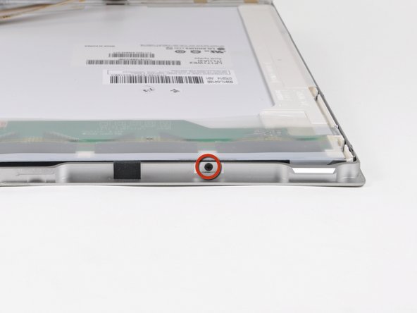
Remove the two 3.2 mm Phillips screws on the top edge of the display.
-
-
-
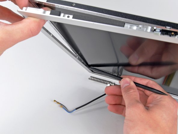
Use the flat end of a spudger to gently lift one of the top corners of the LCD out of the front bezel.
-
-
-
Work your way along the top edge of the LCD, slowly prying the attached steel strip away from the front bezel.
-
Continue prying the LCD off the front bezel along the left side of the display.
-
-
-
Now that the top and left edges are free, slightly lift the LCD out of the front bezel for enough room to pry the steel strip along the lower edge of the LCD away from the front bezel.
-
Pry along the lower edge of the LCD until it is freed from the adhesive on the front bezel.
-
-
-
Lift the LCD out of the front bezel, minding any cables that may get caught.
-
Replacement Note: there are clear plastic spacers attached via adhesive to the sides and bottom of the lcd panel. Be sure to transfer these spacers to the replacement panel for optimum fit.
-


To reassemble your device, follow these instructions in reverse order.
To reassemble your device, follow these instructions in reverse order.
Отменить: Я не выполнил это руководство.
49 участников успешно повторили данное руководство.

2 Комментариев
If you don't mind downgrading the resolution from 1680x1050 to 1440x900, you can use another LCD Panel used for 17" Toshiba laptops: LTN170X2-L02. It's almost the same size and spec-wise, except for the lower res...and can be found much cheaper ($50 to $80). The only caveat is that the backlight cable comes out in a slightly different place, and you have to dremel away some of the lid so it doesn't pinch the backlight cable. I was interested to see if the Mac would recognize it, as 1440x900 was not one of the official resolutions mentioned in the original MacBook specs, but it worked!
Before upgrading to a larger HD, you'll want to "clone" your original HD using the donation-ware program "Carbon Copy Cloner" (http://www.bombich.com/). Put the new HD in an external case; clone the original; test the clone (by starting up with it), then take apart the MacBook to put the new HD in the MacBook, and the original in the external case for use as a backup, etc. (You can't just drag the contents of the original HD to the new HD, and expect it to work; not since the days of OS 9 and before.)
amiller770 - Ответить
Can I put more than two gigabytes of RAM in?
Noah Nsangou - Ответить
mine has 2g*2=4 gb ram in. you should be fine
on mac forum it suggested to put 4gb and a 2gb in a1261.
david -
I made the mistake of wanting to do a clean install of OS and start fresh after installing a SSD. Now I can't install most browsers on OSX Leopard. Does anyone know what is the most current version of OS I can put on this system? (disk or download) Can I get to Snow or Lion?
2006 17" MackBook Pro Model#A1151
2.16 GHz Intel Core Duo
Memory: Two 1GB 667 MHz
Hard Drive: Corsair Force GS: SSD 128GB
scannon - Ответить
You can install OS X 10.7 LION and no later version. Although LION runs ok with 2GB RAM it does help to get 1GB + 2GB = 3GB. Even if you install 2 X 4GB you will only utilize 3GB. Installing a SSD seems to make no difference since the SATA bus is only 1.5GB/s. A good 5400rpm disk is good enough. I even run BootCamp and Windows 7. Works fine. Not fast but fine. My A1212 refuses to die :-)
asle -
There seems to be some discrepancy about whether or not installing a SSD will help. See Phil's earlier comment from October 2015: there, *he* claims that having an SSD increases the load times significantly, (even though -- of course -- 1.5Gbps is not ideal)...
His quotation, (re-)cited integrally:
Just replaced my old HD with a Corsair Force LX SSD (which is SATA 1-3 compatible as required by this model) with success now my old 'outdated' laptop has super fast loading times and is postively flying faster than the speed of 'sound'. Thanks for the guide. Only problem I faced was replacing the top panel which after a few minutes of panic realised the rubber mounted Mic next to the left speaker had risen up when I had removed the top panel so after carefully pushing it back into place the panel fitted back how it should, so beware of this possible problem.
Phil - 10/07/2015
at0gjm -
Bonjour j'ai besoin de cette bactérie que dois-je faire ?
basile kouamé YAO - Ответить