Введение
Tired of only being able to get a 2D top view of your games? Replace the upper LCD and get back to your 3D gaming experience.
Выберете то, что вам нужно
-
Инструмент, используемый на этом этапе:Phillips #00 Screwdriver$5.49
-
Use a Phillips PH00 screwdriver to loosen the four screws along the top of the back cover.
-
-
-
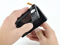
Grab the top edge of the back cover with your opposite hand so that the cover does not fall back into place.
-
Pull the back cover up and away from the rest of the device to remove it.
-
-
-
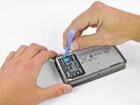
Insert a plastic opening tool into the notch in the lower case above the battery.
-
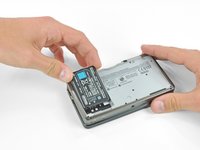
Pry the battery up with the plastic opening tool.
-
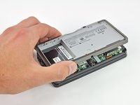
Grab the top edge of the battery and lift it out of the lower case.
-
-
-
Use a JIS #00 screwdriver to remove the nine 6.3 mm black screws from the lower case.
-
Use a JIS #00 screwdriver to remove the 2.4 mm silver screw above the game cartridge slot.
-
-
-
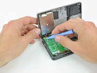
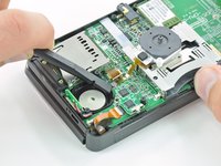
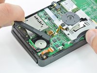
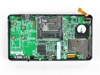
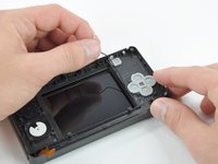
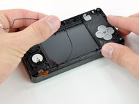
Lift the bottom edge of the lower case off the rest of the 3DS.
-
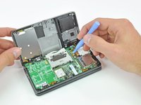
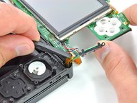
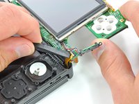
Use a plastic opening tool to pry the shoulder button ribbon cables off their sockets on the motherboard.
-
Remove the lower case from the device.
-
-
-
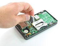
Remove the two 7.7 mm Phillips screws securing the back of the Circle Pad to the motherboard.
-
-
-
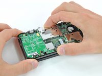
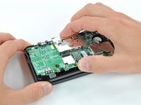
Use the flat end of a spudger to pry the back of the Circle Pad off the motherboard.
-
Lift the Circle Pad joystick off the motherboard and lay it on its back so that the ribbon cable connector is accessible.
-
-
-
Use the flat end of a spudger or your fingernail to flip up the retaining flap on the Circle Pad ribbon cable ZIF socket.
-
Lift the Circle Pad joystick off the motherboard.
-
-
-
Use a spudger or screwdriver to lift the pads up and remove them from the device.
-
-
-
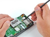
Remove the two 4.5 mm Phillips screws securing the SD board to the motherboard.
-
-
-
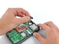
Use the flat end of a spudger to pry the SD board ribbon cable connector off its socket on the motherboard.
-
-
-
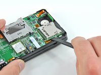
Insert the flat end of a spudger between the SD board and the motherboard.
-
Pry up slowly to loosen the SD board from the RF shield underneath it. If you pry too quickly, you may tear the shield or break its solder points.
-
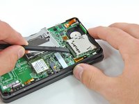
Run the spudger along the sides of the SD board to free it from the adhesive holding it in place.
-
Once completely freed, lift the SD board straight off the motherboard.
-
-
-
Slide the flat end of a spudger under the corner of the Wi-Fi board, and lift it away from the motherboard.
-
-
-
Use the flat end of a spudger to pry the Wi-Fi antenna cable connector off its socket on the Wi-Fi board.
-
Remove the Wi-Fi board from the device.
-
-
-
Инструмент, используемый на этом этапе:Tweezers$4.99
-
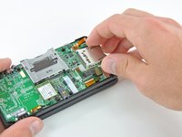
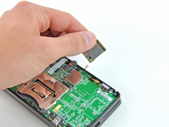
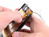
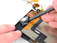
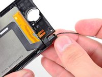
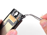
Grasp the microphone ribbon cable near the microphone with a pair of tweezers.
-
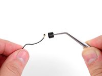
Pull the microphone straight up out of the upper case.
-
-
-
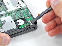
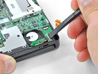
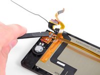
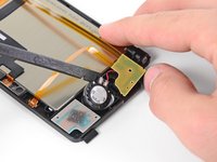
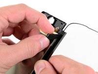
Use the flat end of a spudger or your fingernail to flip up the retaining flap on the speaker assembly ribbon cable ZIF socket.
-
Disconnect the speaker assembly ribbon cable with a pair of tweezers.
-
-
-
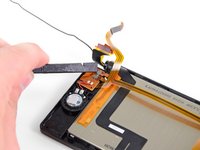
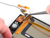
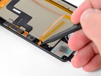
Use the flat end of a spudger or your fingernail to flip up the retaining flap on the camera ribbon cable ZIF socket.
-
-
-
Remove seven Phillips screws securing the motherboard to the upper case:
-
Four 2.5 mm gold screws
-
Two 3.5 mm black screws
-
One 2.5 mm silver screw
-
Lift the side of the motherboard that sits along the bottom edge of the 3DS.
-
-
-
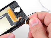
Use the flat end of a spudger or your fingernail to flip up the retaining flap on the LCD ribbon cable ZIF socket.
-
-
Инструмент, используемый на этом этапе:Tweezers$4.99
-
Before continuing with disassembly, use a pair of tweezers to remove the clear plastic diffuser for the wireless notification LED. The small piece is likely to fall out on its own, and may be difficult to find if it lands on the floor.
-
-
-
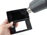
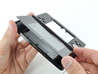
Heat the edges of the upper display front panel with a hair dryer or heat gun to soften the adhesive holding it to the display bezel.
-
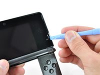
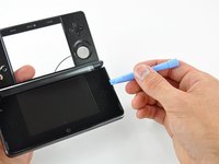
Begin prying the edges of the front panel off with a plastic opening tool.
-
-
-
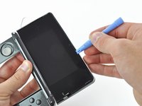
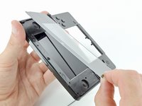
Continue prying the remaining sides of the front panel by sliding the plastic opening tool down each edge.
-
-
-
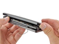
With all of the sides free, lift the upper display front panel off the display bezel.
-
-
-
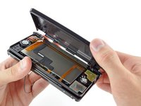
Remove the six 3.6 mm Phillips screws securing the rear display bezel to the front display bezel.
-
-
-
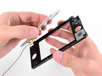
Lift the edge of the rear display bezel closest to you and rotate it towards the hinge.
-
Continue to lift the rear display bezel off the rest of the device until it is free.
-
-
-
Remove the 3D adjustment switch from the front display bezel.
-
-
-
Insert a metal probe into the space above the ABXY buttons with the point touching the metal hinge.
-
Push the hinge towards the center of the upper case. This will require a fair amount of force.
-
-
-
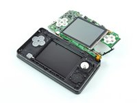
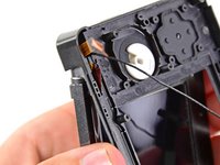
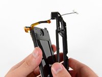
Slowly pull the upper display assembly away from the upper case.
-
Make sure that the various ribbon cables are being fed through the slit in the upper case.
-
Separate the upper display assembly from the upper case.
-
-
-
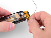
Carefully feed the speaker assembly ribbon cable through the hole in the upper display bezel.
-
-
-
Remove the 2.5 mm Phillips screw securing the right speaker board to the upper display bezel.
-
-
Инструмент, используемый на этом этапе:Tweezers$4.99
-
Use the flat end of a spudger or your fingernail to flip up the retaining flaps on the parallax barrier ribbon cable ZIF sockets.
-
Use a pair of metal tweezers to disconnect the two ribbon cables.
-
-
-
Use the flat end of a spudger to pry the left and right speakers out of their places in the upper display bezel.
-
Pry the camera status LED out of the upper display bezel with the tip of a spudger.
-
-
-
Gently roll the upper LCD ribbon cable and camera ribbon cable together and insert them into the hinge opening.
-
-
Инструмент, используемый на этом этапе:Tweezers$4.99
-
Use a pair of metal tweezers to remove the black metal hinge ring from the upper display bezel.
-
Carefully pull the camera and upper LCD ribbon cables through their hole in the upper display bezel.
-
-
-
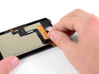
Peel the camera ribbon cable off the back of the upper LCD.
-
Remove the camera ribbon cable assembly.
-
-
-
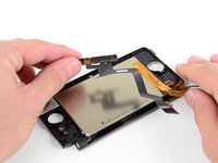
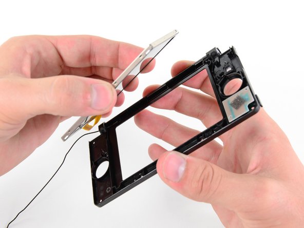
Use your thumbs to push the upper LCD from the front out of the upper display bezel.
-
Remove the upper LCD.
-
-
-
A strip of black adhesive tape holds the upper LCD to the display bezel. Use the tip of a spudger to remove the tape from the LCD housing.
-


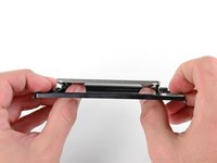

To reassemble your device, follow these instructions in reverse order.
To reassemble your device, follow these instructions in reverse order.
Отменить: Я не выполнил это руководство.
73 человек успешно провели ремонт по этому руководству.

23 Комментариев
Thanks very much for this. After two different electronic repair shops had refused to replace the broken top screen in the 3DS which our daughter had borrowed from a friend, I reluctantly decided try it myself, having studied this guide a couple of times.
It took me over 4 hours, almost an hour of which was just getting the 3 ribbon cables out through the hinge and back in again. It was incredibly satisfying to power it up again and have everything work. Without this detailed guide and photographs, I would certainly have given up.
Use good quality screwdrivers!
This is one of the hardest repairs for this console too, great job doing it on your own. I've been fixing electronics for a while and this one is still scaring me lol
All the commentors talking about how they stripped the screws are obviously not using the correct screwdriver - they're phillips #00 screws and they come out easily. You don't need to buy an expensive speciality screwdriver, just do it properly. Make sure the driver grips the screw properly, apply a moderate amount of pressure, and turn it slowly. It isn't hard at all. The only thing I can think is that everyone stripping the screws is using one of those screwdrivers with the head shaped like an 8 pointed star. Those will strip screws easily and are easy to mistake for the usual + shaped screwdriver. The one I used comes from a Black & Decker precision screwdriver set. I think it was £7 from Homebase.
Dear colleagues of gaming
My son dropped the 3DS, and this is the result:
https://www.dropbox.com/s/0t5p5enpdu1d6g...
can you tell me your opinion, is the substitution of the lcd necessary and/or sufficient? The glass (external) is not broken.
Thank you