Эта версия возможно содержит некорректные исправления. Переключить на последнюю проверенную версию.
Выберете то, что вам нужно
-
Этот шаг не переведен. Помогите перевести
-
Insert a SIM card eject tool, bit, or a straightened paperclip into the small hole below the SIM card tray, located near the rear cameras on the edge of the phone.
-
Press firmly to eject the tray.
-
-
Этот шаг не переведен. Помогите перевести
-
Remove the two 2.6 mm T2 screws straddling the USB-C port on the bottom edge of the phone.
-
-
Этот шаг не переведен. Помогите перевести
-
Display panel seam: This seam is part of the display assembly. Do not pry at this seam, or you will separate and damage the display panel.
-
Frame seam: This is where the plastic frame meets the back cover. Only pry at this seam.
-
There are twelve clips that hold the frame against the rear case. Be aware of their location as you pry the back cover off in the following steps.
-
-
Этот шаг не переведен. Помогите перевести
-
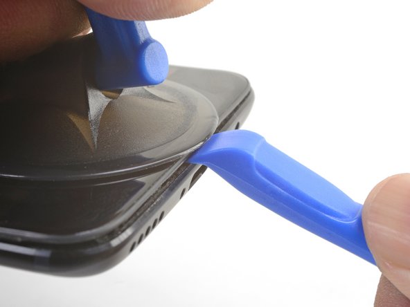
Place a suction cup near the bottom edge of the display.
-
Pull on the suction cup with strong steady force.
-
Press the edge of an opening tool straight into the frame seam near the suction cup until the edge wedges between the plastic frame and the back cover's lip.
-
-
Этот шаг не переведен. Помогите перевести
-
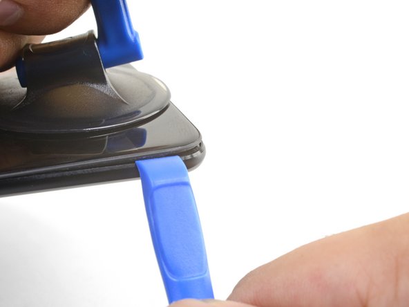
Once the opening tool's edge is wedged in position, carefully slide the tool along the bottom edge of the phone.
-
Carefully guide the opening tool around the left corner of the phone while keeping the tool's edge within the seam.
-
-
Этот шаг не переведен. Помогите перевести
-
Lever the opening tool to release the first clip from the frame.
-
-
Этот шаг не переведен. Помогите перевести
-
Continue sliding the opening tool along the long edge, releasing the clips along the way.
-
-
Этот шаг не переведен. Помогите перевести
-
With the bottom and left edge of the phone freed, gently wiggle the frame to release the top and right edge clips.
-
Align the top edge of the frame to the back cover and ensure that the top clips slip into place.
-
Squeeze along the long edges of the phone to snap the remaining clips into place.
-
-
Этот шаг не переведен. Помогите перевести
-
With all the clips released, flip the phone over so that the display is face-down.
-
Swing the back cover around and rest it on top of the exposed frame.
-
-
-
Этот шаг не переведен. Помогите перевести
-
Remove the 2.6 mm Phillips screw holding the cable bracket above the battery in place.
-
Lift up and remove the cable bracket.
-
-
Этот шаг не переведен. Помогите перевести
-
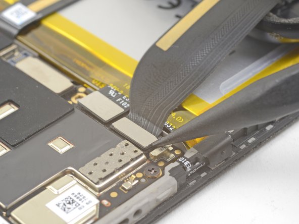
Use the point of a spudger to pry up and disconnect the back cover flex cable from its socket.
-
-
Этот шаг не переведен. Помогите перевести
-
Use the point of a spudger to pry up and disconnect the battery connector from its socket.
-
-
Этот шаг не переведен. Помогите перевести
-
Remove the six 2.6 mm Phillips screws securing the loudspeaker to the frame.
-
-
Этот шаг не переведен. Помогите перевести
-
Insert the flat end of a spudger into the corner of the loudspeaker assembly and pry slightly, loosening the loudspeaker from its recess.
-
-
Этот шаг не переведен. Помогите перевести
-
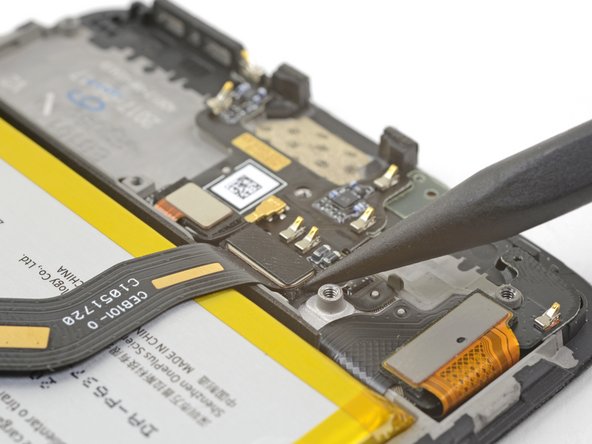
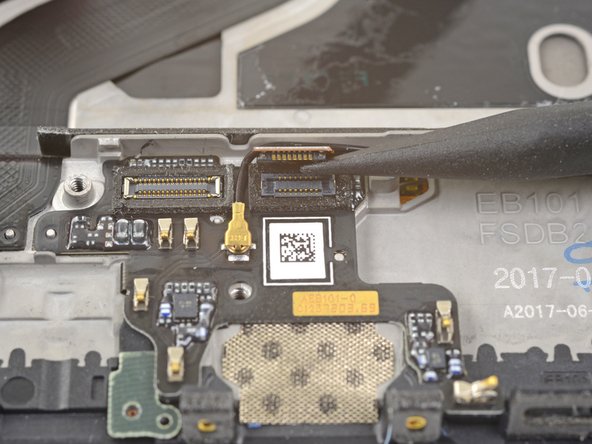
Use the point of a spudger to pry up and disconnect the interconnect flex cable from the socket.
-
-
Этот шаг не переведен. Помогите перевести
-
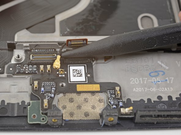
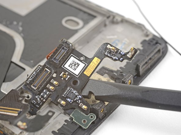
Use the point of a spudger the pry up and disconnect the fingerprint scanner connector from its socket on the daughterboard.
-
-
Этот шаг не переведен. Помогите перевести
-
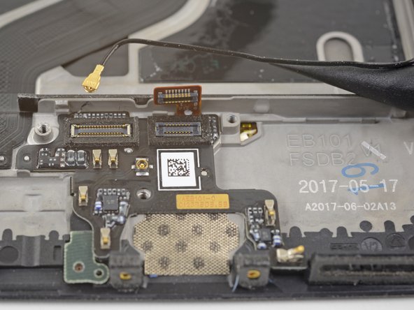
Slip the point of a spudger underneath the antenna interconnect cable and pry up to disconnect it from its socket on the daughterboard.
-
De-route the antenna interconnect cable out of the way of the daughterboard.
-
-
Этот шаг не переведен. Помогите перевести
-
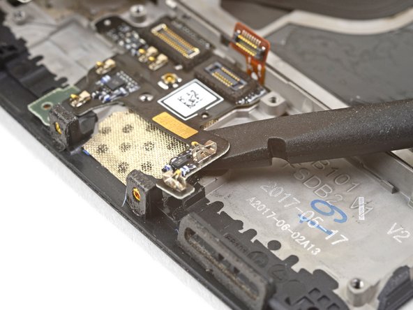
Insert the edge of a flat end of the spudger underneath the microphone board and twist slightly to release the board's adhesive.
-
-
Этот шаг не переведен. Помогите перевести
-
Slide the flat end of a spudger or the point of an opening pick underneath the daughterboard near its right edge.
-
Gently pry to loosen the daughterboard from its recess.
-
-
Этот шаг не переведен. Помогите перевести
-
Insert the flat end of a spudger underneath the daughterboard, this time approaching it from the bottom.
-
Twist and slide the spudger slightly to release the daughterboard from its recess.
-
-
Этот шаг не переведен. Помогите перевести
-
Slide the flat end of a spudger underneath the tape covering the fingerprint scanner.
-
Lift up to pry and remove the tape.
-
-
Этот шаг не переведен. Помогите перевести
-
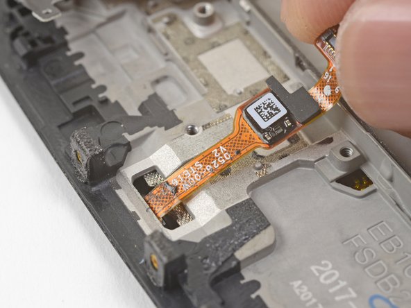
Use your finger to gently lift up the connector end of the fingerprint scanner. Pull upwards slowly. Do not pull directly away from the fingerprint scanner.
-
Keep pulling upwards until the fingerprint scanner cable is freed from its recess.
-
-
Этот шаг не переведен. Помогите перевести
-
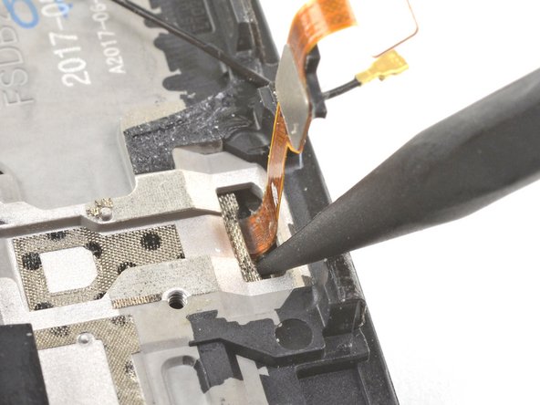
Insert the point of a spudger into the marked areas on either side of the flex cable, and push until the fingerprint scanner is loosened from its recess.
-
-
Этот шаг не переведен. Помогите перевести
-
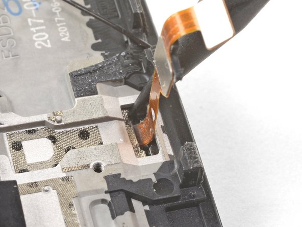
Once the fingerprint scanner is loosened from its recess, carefully thread its flex cable through the cutout, out of the front of the display.
-
Remove the fingerprint scanner.
-


Отменить: Я не выполнил это руководство.
Еще один человек закончил это руководство.


8 Комментариев
Is there an extra step involved so that the button stays countersunk in the new display? Mine seems to be slightly proud of the screen
Hi John,
If you may need to apply some new adhesive to the underside of the fingerprint sensor to hold it in place.
Hi,
I change the fingerprint but only works if don’t close the back cover, when I close the back cover the OS don’t detect the fingerprint sensor. Any idea?
Hey César,
It may be that something is shorting the fingerprint sensor. Did you replace the tape in step 24 with electrical tape?
Great news, finally I found the problem, the connector from daughter board to motherboard was disconnected but a lot of pins maked contact and the micro, and other electronics works but not the fingerprint sensor. I dissasembled the motherboard and pushed the connector from the flex cable to the socket, now all is working ok. Thanks for the response Arthur!