Введение
The Terracopter EVO controller motherboard is used to control all of the functions of the controller and relay them to the drone.
Выберете то, что вам нужно
-
-
Using a Phillips #0 screwdriver, remove the screw connecting the battery cover to the controller.
-
Remove the battery cover from the controller.
-
-
Шаг 3 Protocol TerraCopter EVO Controller Opening
Внимание: шаги 3-4 взяты из руководства, помеченного как незавершенное.
-
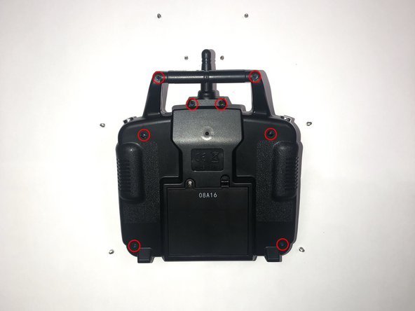
Orientate the controller to where the battery compartment is facing upwards.
-
Remove the four 5mm and four 4mm Phillips #1 screws from the case.
-
-
-
-
Since the battery wires are still attached, carefully move the rear panel down to expose the motherboard.
-
-
-
Remove the eight 5mm Phillips #1 screws from the motherboard.
-
-
-
Locate the set of four green wires and one black wire attached to the motherboard.
-
Remove the male, white connector by pressing up on the two tabs on the female connector. Then, pull the connector away from the female connector on the motherboard
-
-
-
Locate the single pin holding the negative and positive wires to the motherboard. Each lead should have one pin holding each wire to the green side of the motherboard.
-
Using a soldering iron, melt the existing solder point for the red lead (positive line).
-
Using a soldering iron, melt the existing solder point for the black lead (negative line).
-
Pull the red and black leads through their respective holes, out of the motherboard.
-


To reassemble your device, follow these instructions in reverse order.
Отменить: Я не выполнил это руководство.
Еще один человек закончил это руководство.
Команда

The Citadel Military College of South Carolina, Team S1-G22, Eggleston Fall 2019 Участник The Citadel Military College of South Carolina, Team S1-G22, Eggleston Fall 2019
CMCSC-EGGLESTON-F19S1G22
3 членов
Автор 3 руководств