Введение
Like brain surgery? Use this guide to replace your logic board.
Выберете то, что вам нужно
-
-
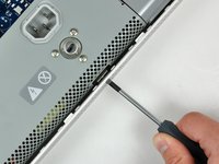
Lay the iMac display-side down on a flat surface.
-
Loosen the three Phillips screws securing the rear panel to the iMac.
-
-
-
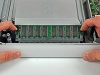
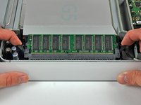
Lift the rear panel slightly from the bottom edge of the iMac.
-
Pull the rear panel toward yourself and remove it from the iMac.
-
-
-
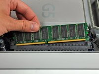
Rotate each of the two RAM retaining arms away from the RAM chip.
-
Pull the RAM chip straight away from its socket.
-
-
-
Remove the three 8 mm brass Phillips screws securing the optical drive to the midplane.
-
-
-
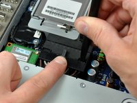
Lift the optical drive near the connector to separate it from the logic board.
-
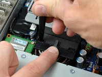
Lift the free end of the optical drive slightly, then pull it away from the edge of the rear case to clear the two plastic positioning pins.
-
Lift the optical drive out of your iMac.
-
-
-
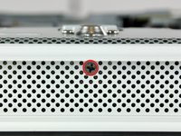
Rotate the center Phillips screw on the bottom of the iMac clockwise until the rear panel clamp contacts the edge of the case.
-
-
Инструмент, используемый на этом этапе:Heavy-Duty Spudger$4.99
-
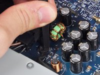
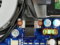
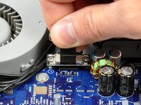
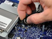
While depressing the connector lock, insert the flat end of a heavy duty spudger into the gap between the power supply connector and its socket.
-
Twist the heavy duty spudger to slightly separate the connector from its socket.
-
-
-
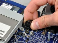
Pull the power supply connector straight away from its socket on the logic board.
-
This step is very simple if you remove the power supply first.
-
-
-
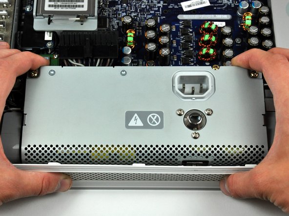
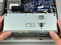
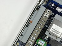
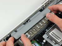
Grab the power supply from each side and rotate its top edge toward yourself until it clears the logic board.
-
Lift the power supply out of the midplane.
-
-
-
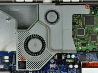
Disconnect the hard drive thermal sensor cable from the hard drive thermal sensor board.
-
-
-
-
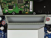
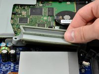
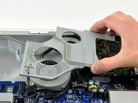
Remove the two 13 mm T10 Torx screws securing the fan duct to the midplane.
-
Lift the fan duct out of the midplane.
-
-
-
Remove the two Phillips screws securing the fan cover to the midplane.
-
Lift the fan cover out of the midplane.
-
-
-
Remove the two 7 mm shouldered Phillips screws securing the display data cable to the logic board.
-
Using its black pull tab, pull the display data cable connector straight up off its socket on the logic board.
-
-
-
Disconnect the SATA power cable by depressing the lock mechanism and pulling the connector straight away from its socket.
-
-
-
Disconnect the SATA data cable by pulling its connector straight up off the logic board.
-
-
-
Disconnect both fans by pulling their connectors straight up off the logic board.
-
On the ALS model, the larger fan connector is attached with a clip. Depress the clip while carefully removing the plug.
-
-
-
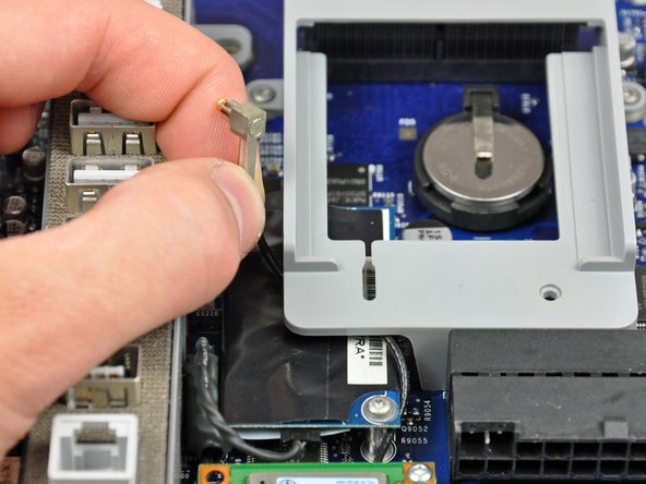
Slide the inverter-to-display cable connector from under the metal clip on the midplane.
-
-
-
Disconnect the inverter-to-display cable connector by pulling it straight away from its socket.
-
-
-
Remove the single 8 mm brass Phillips screw securing the inverter to the logic board.
-
Lift the inverter straight up off the pins on the logic board.
-
-
-
Disconnect the inverter cable from the logic board by pulling it straight up from its socket.
-
-
-
De-route the inverter cable connector from the channel in the logic board.
-
Lift the inverter out of the midplane and set it aside.
-
Skip this step if yours is an ALS model; this part is not present.
-
-
-
Use the tip of a spudger to lift the speaker cable connector from its lower edge straight up off the logic board.
-
-
-
Insert the tip of a spudger into the center hole punched into the side of the lower fan connector.
-
With the spudger still inserted, lift the lower fan connector straight up off the logic board.
-
-
-
Use the tip of a spudger to lift the microphone cables enough to grab the microphone cable connector and pull it straight up off the logic board.
-
-
-
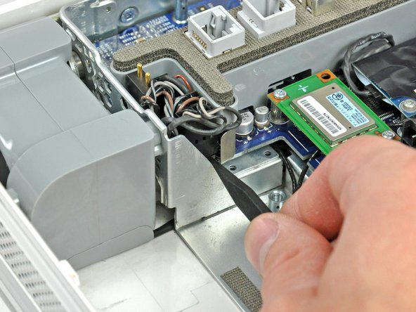
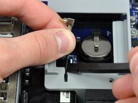
Using its attached pull tab, lift the AirPort card slightly and pull it straight away from its socket.
-
This step does not apply to the ALS model; this bracket is not present. The card attaches with a pair of T6 Torx screws and looks slightly different from this picture.
-
-
-
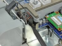
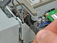
Insert the flat end of a spudger between the antenna connector and the body of the AirPort card.
-
Push the spudger away from the AirPort card to disconnect the AirPort antenna.
-
This step does not apply to the ALS model.
-
-
-
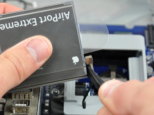
Use a spudger to push the AirPort antenna cable through the slot in the AirPort card bracket.
-
De-route the AirPort antenna out from under the AirPort bracket.
-
This step does not apply to the ALS model.
-
-
-
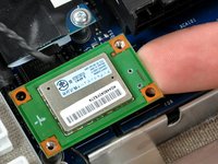
Remove the two T6 Torx screws securing the Bluetooth board to the logic board.
-
Some models may not have a blue tooth module.
-
-
-
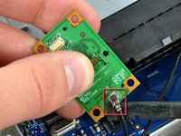
Depending on your iMac model, the bluetooth board may be blue. Use your fingertip to lift the Bluetooth board from its right edge, disconnecting it from its socket on the logic board.
-
Use the flat end of a spudger to pry the Bluetooth antenna connector up off the Bluetooth board.
-
-
-
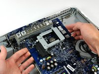
Remove the following nine screws securing the logic board to the midplane:
-
Six 7 mm T10 Torx.
-
Three long 20 mm brass coarse-thread Phillips.
-
-
-
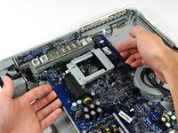
Lift the logic board from its left edge to clear the two positioning pins connected to the midplane.
-
-
-
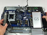
Grab the logic board from both edges and lift it out of the midplane, minding any cables that may get caught.
-


To reassemble your device, follow these instructions in reverse order.
To reassemble your device, follow these instructions in reverse order.
Отменить: Я не выполнил это руководство.
61 человек успешно провели ремонт по этому руководству.
