Введение
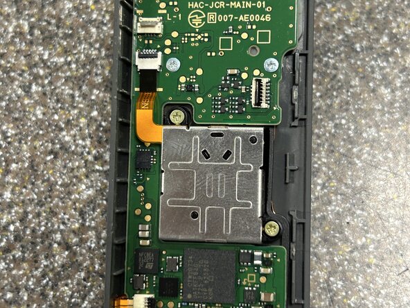
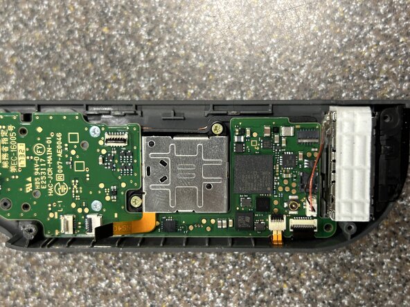
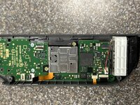
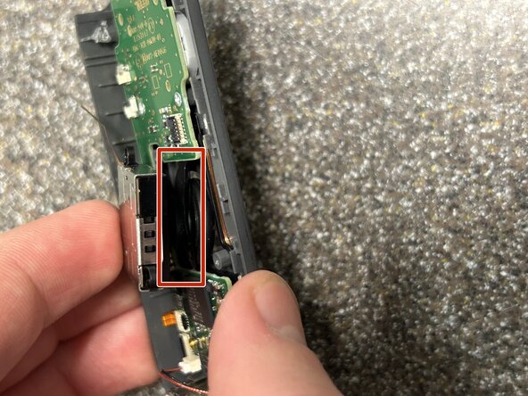
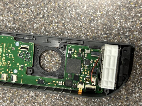
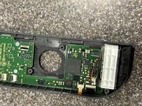
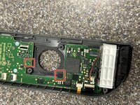
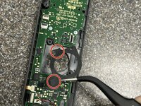
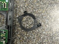
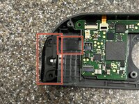
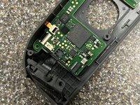
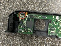
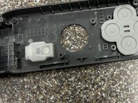
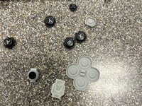
This guide aims to show how to completely disassemble your right joycon without hurting any parts. This disassembly is more difficult than the right joycon due to the additional IR sensor, Bluetooth antenna, and NFC reader.
In this guide I refer frequently to the iFixit Phillips PH000 which is designed to work with JIS screws. The screws in the Nintendo Joy Con are, if I understand it correctly, JIS screws which iFixit sells drivers for separately as well.
Выберете то, что вам нужно
-
Инструмент, используемый на этом этапе:iFixit Opening Picks (Set of 6)$4.99
-
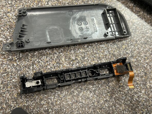
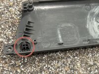
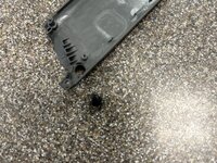
To separate the shell halves there are two options:
-
1. Use an opening pick and insert it between the IR sensor and the other half carefully prying them apart
-
2. Push up on the rail towards the shell halve not attached to the IR sensor
-
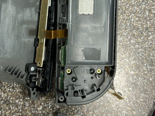
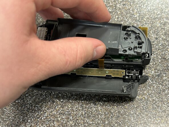
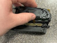
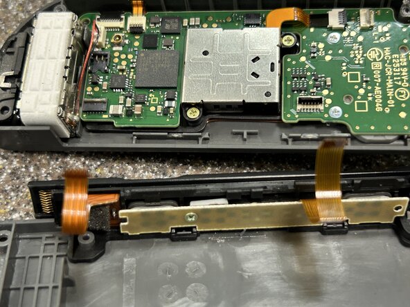
With the shell halves separated, carefully put the side with the rail next to the other half
-
-
-
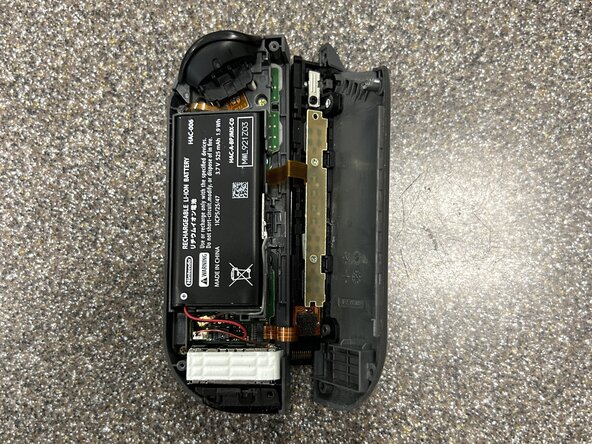
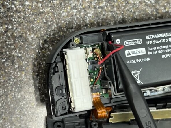
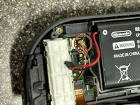
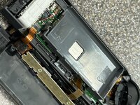
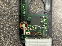
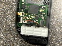
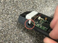
With the battery disconnected, disconnect the bluetooth antenna and pull it out of its compartment carefully
-
-
-
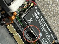
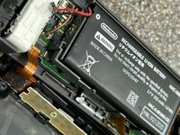
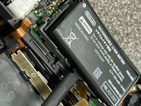
Using an opening pick or the flat side of the spudger, pry up the battery from beneath it.
-
-
-
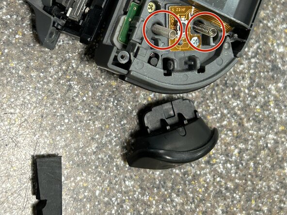
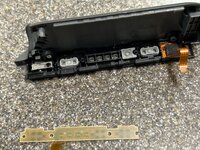
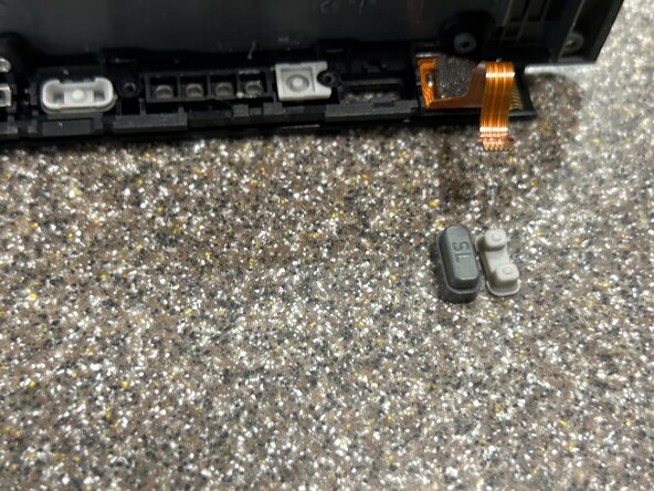
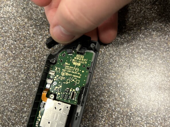
Insert the flat side of the spudger or the opening pick between the ZR button and the upper bracket. Lift up on the ZR button until the clips disengage and you can carefully remove it.
-
-
-
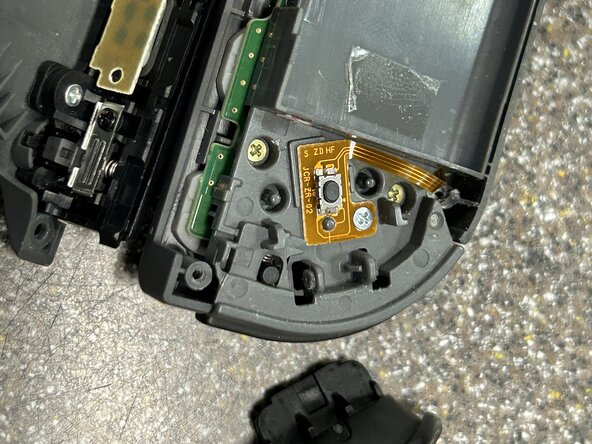
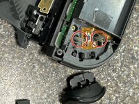
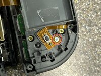
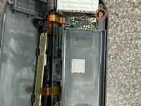
Using a Phillips PH000 screwdriver, remove the screw holding down the flex cable and button
-
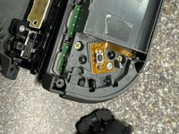
Lift up the flex cable and button board using the spudger to disconnect it from the bracket
-
-
-
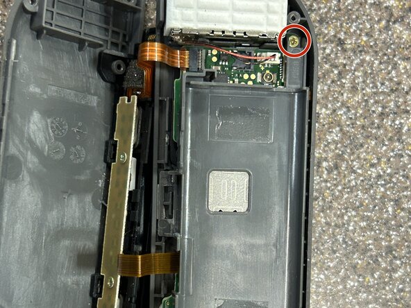
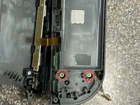
Remove the three Phillips PH000 screws holding down the upper bracket and pull the bracket off the motherboard
-
-
-
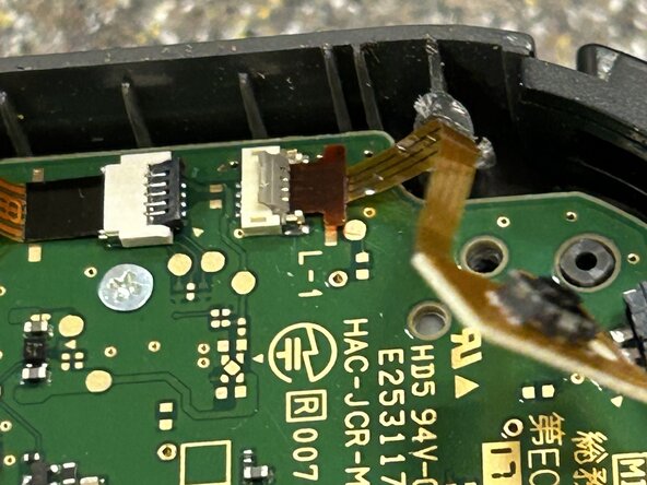
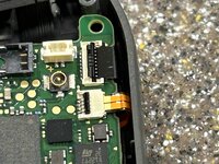
Flip up the ZIF connector lock holding in the ZR trigger button cable with the tip of the spudger and remove the flex cable
-
-
-
-
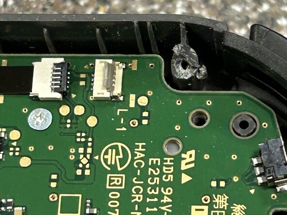
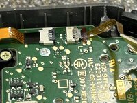
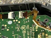
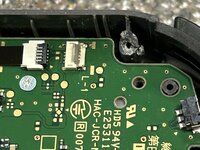
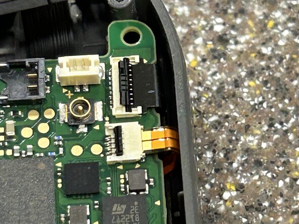
Flip up the ZIF connector locks holding in the rail ribbon cables and remove the flex cables
-
-
Инструмент, используемый на этом этапе:Phillips #00 Screwdriver$5.49
-
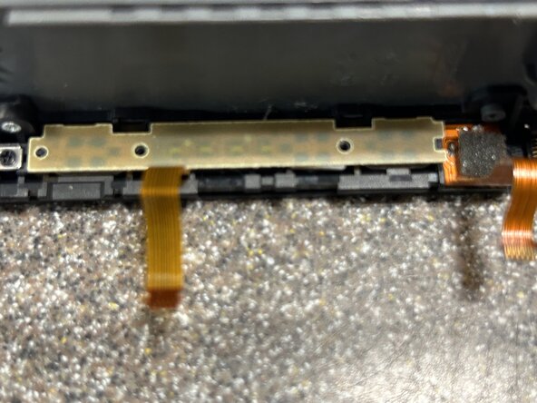
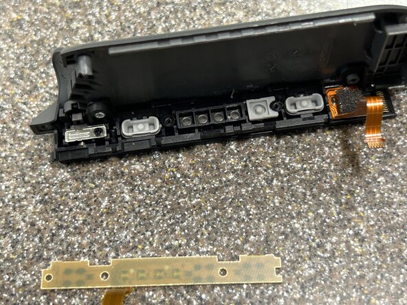
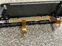
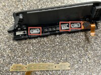
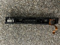
Working on the charging rail, remove the two Phillips PH000 screws holding down the buttons
-
-
-
Remove the last Phillips PH000 screw in the rail holding down the buckle lock
-
-
-
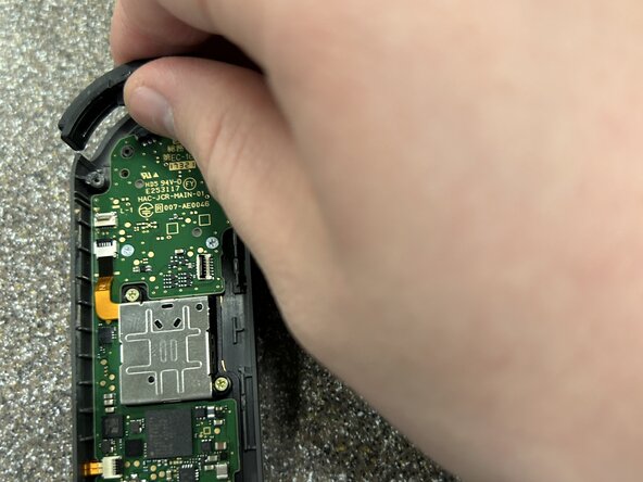
Carefully remove the R trigger button by pulling it up and out of the upper chassis
-
-
-
Carefully remove the joystick liner by pulling up on it with tweezers and lightly pulling on the sections adhered to the upper chassis
-
-
-
Flip up one of the ZIF connectors (I will not be responding to messages at this time regarding the allegation I forgot to disconnect the second cable until later on)
-
-
-
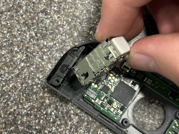
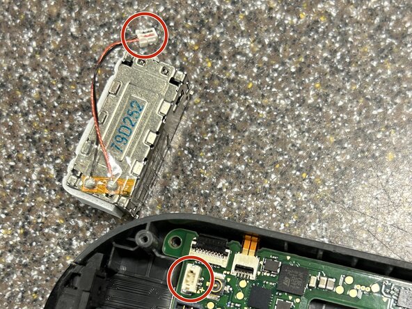
Remove the rumble pack by prying up on the corner next to where the rail once was with a spudger. Once out of its socket, use tweezers to pull the cable connector out of the socket. It is inserted quite firmly so be careful not to hurt the cable and use your fingernails if needed
-
-
-
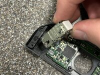
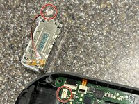
Carefully pull the IR sensor out of its socket making sure not to tear the ribbon cable connected to its button
-
-
-
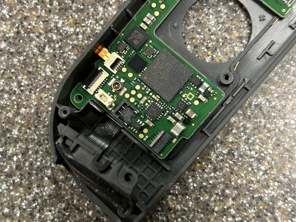
Flip the final ZIF connector, detach both cables, and remove the motherboard (again, as I mentioned in step 22, I am not responding to any allegations regarding forgetting to flip this ZIF cable earlier)
-
-
-
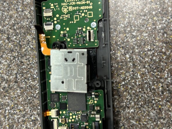
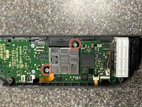
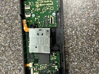
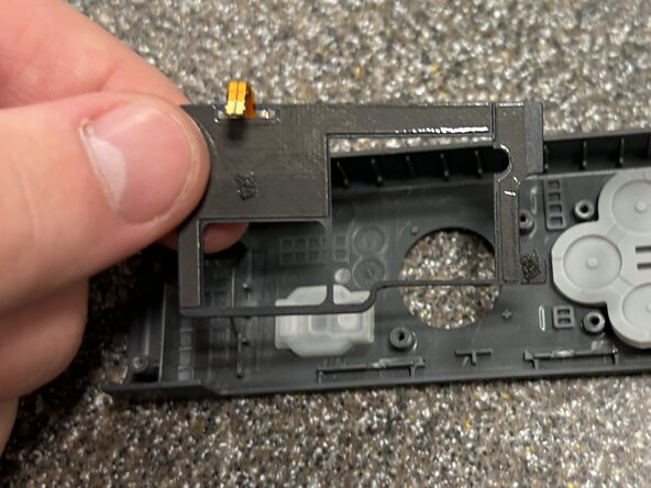
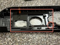
Remove the adhered NFC reader by prying up on an edge carefully and pulling up on other areas until it can be safely removed (marked is the corner I pulled up from)
-


