Peavey Valve King 100 doesn't seem to be getting power...no power light or any kind/type of sound. Have checked power cord even tried different ones. Have checked electrical outlet, even tried different ones.
Amp got turned over while playing, but wasn't dropped. It did break input jack, but was still able to play through it.
It started blowing outside fuse beside power jack on back where electrical cord plugs in. Took all of tubes out and systematically replaced one at a time until found the one blowing fuse. Amp worked for a while at home, but when I took amp out to friends house to practice with band, it just died...stopped all together, and wouldn't power up any more.
Can't afford new amp so advice to fix it will be deeply appreciated.
Прокрутите эту тему, чтобы найти подходящее место для этого комментария. Затем нажмите "Прикрепить комментарий к этому сообщению", чтобы переместить его.
1 Комментарий
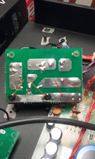
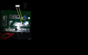
here's picture of circuit board [3] where F204 fuse holder is mounted...red arrow points to where solder seems to be missing...not sure, but maybe point of problem?...
Do you know how to use a DMM and how to read circuit diagrams?
If not, as there are hazardous, even lethal voltages inside the amp, if you don't know how, because you will need to know to find the problem, then I recommend that you contact a reputable, professional electronics repair service and ask for a quote to repair the amp.
Just so that you are aware that there are hazardous and possibly lethal voltages present.
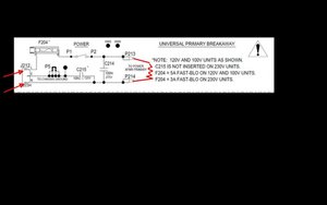
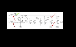
Here is an image showing the input circuit to the power transformer. You can perform a static test on this circuit to prove it is OK, i.e. test it with the power disconnected completely from the amp
It is taken from a Peavey Valve King 100 (212)(which I hope that yours is), circuit diagram Forgive the crude additions made by me.
(click on image to enlarge for better viewing).
Using the Ohmmeter function found in a DMM, place the Ohmmeter test leads across the Line and Neutral connectors in the amp power input socket (as shown by the 2 red arrows) and operate the Power switch on the amp. There should be a reading on the meter, because the meter is 'seeing' the primary winding (red squiggly line) of the power transformer. If there is no reading, first check that the DMM is set correctly for Ohms (s/c the test leads to prove that the DMM works and you read 0 (zero) Ohms), if still no reading across the power input terminals with the Amp Power switch on, then you have to do a point to point test of the circuit. Start with one test lead on the L connection in the socket (leave it there and only move the other lead) then place the other lead on the F204 fuse and see if the meter shows a reading. If it does move the test lead to the next point in the circuit, the Power switch and check there and so on until you find out where there is no longer any meter reading. The problem lies between where the two readings, one good the other bad are. The problem could either be dry solder joints, broken or loose connections or even a loose fuse holder, etc. If you find that there is no reading 'through' the Transformer (P213 & P214) the winding is o/c, OR perhaps the connections to the windings are broken or dry solder joints.
If the power input circuit tests OK then this image is of the valve heater circuit and also the Power On LED. If there is no valve heater power supply then the valves won't work even if the other power supplies to the valves are OK. They won't 'glow'. I'm old enough to have been taught how valves work so as to be able to work on circuits containing them (national telephone network transmission circuits), transistors were the new kids on the block back then. ICs were yet to come
(click on image to enlarge for better viewing).
Initially test directly across P211 & P215. You should get a low reading. This is one of the secondary windings of the power transformer. If you get no reading at all, again check the connections to this winding.
If this winding tests OK then you now have to test with the power on.
Be aware of the dangers! You now have to use the DMM as a Voltmeter.(set to Volts DC initially highest range to safeguard the DMM). If you can, use the DMM with alligator clips on the end of the test leads. That way you can connect the meter leads to the test points before turning on the power so that you are not in anyway touching anything inside the amp with the power on.
Always switch off the power, on the Power switch and also the wall outlet before reaching into the amp.
Place the test leads between the chassis of the amp (ensure a good bright metal connection point) and either the valves heater connection (HTR - or the other side of R212 from which the +14V test point is connected) or +14V test points (which you will have to find on the circuit board). Connect the power to the amp and switch on. You should get a reading around 14V DC on the DMM. if there is no reading there may be a problem with Fuse 203, the diodes D206 - D209, R213, R212 or any connection between them.
Hopefully this is of some help. Be careful and stay focused on what you are doing
Update (04/04/2017)
Hi Keith,
Thanks for the pictures it really helped.
I think that the problem in on the pad below the fuse that the P1 wire is connected to. I maybe wrong of course.
Here is an image of what I think the fuse connections are from the Line input and the P1 switch.
(click on image to enlarge for better viewing)
Put the fuse back into the holder, with the cap to hold it in. Then place the Ohmmeter test leads across the two pads as shown in the image. If you do not get a reading then there is a problem with either one of the two connections, (basically where the arrowheads are) or the fuse holder itself. I'm leaning towards the "P1"end of the fuse pad connection being the one. Also try "moving"the fuse holder (you said it was loose) to see if the reading comes and goes. Either way hit both of them with a soldering iron to melt the solder to establish a good connection.
If you cannot get a reading between the two fuse connection solder pads with the fuse in AND you have resoldered the connections then the actual fuse holder is faulty and will have to be replaced.
Just playing devil's advocate, have you got the correct sized fuse inserted? Not the rating of the fuse but its' dimensions, so that it will touch the connections inside the holder OK. Have a look inside the holder with a torch and magnifying glass to work out how the fuse ends 'touch the terminals inside the holder. If you cannot get a replacement fuse holder to fit then you may have to "jury rig" an alternative such as an appropriate inline fuse or something similar.
To verify that the fuse connection or the fuse holder itself is the problem, connect the meter between the fuse's P1 "solder pad" and the P1 switch terminal and you should get a reading. If so operate the switch and connect the meter between the fuse's P1 "solder pad" and the Neutral input terminal. If there is a reading this proves the circuit from the fuse "output" through the Power transformer all the way to the power input. Next place the meter between the fuse's Line "solder pad" and the Line input terminal. You should also get a reading. This proves the circuit to the fuse's "input".
Прокрутите эту тему, чтобы найти подходящее место для этого комментария. Затем нажмите "Прикрепить комментарий к этому сообщению", чтобы переместить его.
33 Комментариев:
thanks for all of the time and concern you've put into this answer...the amp has been unplugged for several weeks now, but I'm sure that there probably may still be some residual electricity stored so I intend on being extremely focused and careful...will get back with you with updates and questions as need be if that's ok...thanks again
Here is a link to the schematics. Scroll down right hand column and click on Peavey Valve King 100 212 link. On the next page that opens enter the verification code, the donate is up to you (you can just click on Download if you wish.
Will try to help if needed but be aware that there most probably is a Time Zone difference so replies might take a while.
You can go down to the 200 Ohm range for more accuracy as to the actual resistance. It doesn't really matter as in this particular part of the circuit the resistance should hopefully be below 200 Ohms anyway.
The only resistance (apart from poor solder joints or connections perhaps) is the transformer winding and that should be low.
There is an o/c (open circuit) between the fuse and the switch, Check the reading thru the fuse itself, (test lead either side of the fuse should be 0 Ohms, fuse might 'look' OK but test it with the meter) then test from the fuse to the switch. Then check that the fuse holder is holding the fuse tight and that it is soldered OK to the board or however it is in circuit.
You check between the points mentioned. If you can, measure straight across the fuse, one lead on one end of the fuse the other lead on the other end of the fuse. Should read 0 Ohms. If it does then leave meter lead on the fuse end leading to the power switch and place the other lead on the Power switch terminal. If you operate the switch it doesn't matter which terminal. You should read 0 Ohms.
If you cannot measure across the fuse because it is in a fuse holder with no access to the end, take the fuse out and measure the fuse itself. Then measure from the fuse holder to the switch. As I don't know how the fuse is mounted you might have to stick the test lead into the fuse holder to do this, You said before that you got 0.01 Ohms from the line to the fuse so that part is OK. You have to verify the path from the fuse to the switch.
If there is no reading between the fuse and the switch (which was indicated by you before ' .....when I touch P1 or P2, I'm assuming that either one is good for checking when power switch is on, I get no reading....'. then you have to find out why not. Visually inspect the fuse connection (is it to the circuit board or it a free mounted fuse holder wired to the switch?) Whatever you have to follow the wiring from the fuse to the switch to find out where it is faulty
measured fuse and tried new fuse...with meter set at 200ohms, reading was 3.4 - 4ohms on both fuses...noticed fuse holder seemed loose...took board [3] out and...
...seems solder for F204 fuse has came loose on one end of holder...see picture above...[maybe problem?...
You probably have affected something when you "turned the amp over" dropped it. These circuit boards are not solid state and are very fragile!
I would suggest you start again replacing tubes, and find out if you have another bad tube. I would start from the last one you replaced and work backwards from there. These are very dangerous and can be lethal, so be very careful when your hands are inside the case! They may have some sort of old capacitor that will store enough power to burn you real bad, or stop your heart when it is unplugged! Be very careful where you put your hands!
Once you get it going again Don't Move It! What ever is loose in there when moved with probably blow again. Your amps traveling days are over, until you can afford a newer amp or have that one repaired.
I would suggest if you are going to be moving your amp around invest in a newer solid circuit board type Amp. The average Joe, where ever you are playing, is not going be sober enough or care that the sound coming from your amp is "pure". Keep it at home for your own enjoyment.
Прокрутите эту тему, чтобы найти подходящее место для этого комментария. Затем нажмите "Прикрепить комментарий к этому сообщению", чтобы переместить его.
1 Комментарий:
Thanks for reply...will remove tubes and put back like before...maybe will find culprit, but think problem is a little bit deeper in amp since last time was blowing external fuse and this time that fuse is ok.
Also not really concerned about the average Joe, but I prefer tube amps.
It is best to take to an experienced musical amp shop. I will try to demystify the tube based electronics. Each tube has a heater filament that causes the cathodes to emit electrons, there are "screens" between the cathode and anode that control the flow of electrons and therefor the amount of amplification.
The heater filaments are all connected in series. the first number in a tube name is the voltage for the heater filament. If a tube is out of its socket then none of the tubes are getting voltage to heat up. The heater filaments are the reason why it takes a few minutes for the amp to warm up and be ready, the cathodes need the heat to emit electrons. Heater filaments are just like the filaments found in lightbulbs.
Vacuum tubes run at fairly high voltage and the circuits can give a nasty shock that may cause muscles to contract as long as the voltage is present. This is a good reason to take the amp to an experienced tech.
You can do some checks and you may find what is shorting out the fuses. Turn off and unplug the amp and wait at least an hour or longer before you open the amp. Look for burn marks on the chassis and on the components. Use a wooden stick or popsicle stick to move wires (just in case of stored electricity) to see under the wires. The tubes get hot and make burn marks surrounding the base, but if you see a resistor or capacitor that is blackened then you should be close to what is shorting the amp.
Peavey makes rugged amps and this one should be able to handle the road after it is repaired. The hard part is to find an experienced repair tech. You can try contacting Peavey for local repair and call ahead for cost of repair.
Прокрутите эту тему, чтобы найти подходящее место для этого комментария. Затем нажмите "Прикрепить комментарий к этому сообщению", чтобы переместить его.
2 Комментариев:
Thanks for reply...have been searching for someone to take amp to. Have it narrowed down to a couple people.
Its now sept 2020 Im a amatuer tech iI have the same problem but thanks to your in put I was able to fix it yes the fuse conection on the pad and one lug on the power line were loose thank you very much
Прокрутите эту тему, чтобы найти подходящее место для этого комментария. Затем нажмите "Прикрепить комментарий к этому сообщению", чтобы переместить его.
1 Комментарий:
thank you for that info problem now fixed now lets move on to my peavey Delta blues amp redid the whole thing all new caps replaced to op amp and the three little transisiters had a high treble squeel now im not getting the pre amp tubes to light up i checked the wire from the two boards and everthing seams fine no sound now I only have a Good 187 fluke meter and a variac to check things out no signel gen or ocilliscope or any high tech equipment


1 Комментарий
here's picture of circuit board [3] where F204 fuse holder is mounted...red arrow points to where solder seems to be missing...not sure, but maybe point of problem?...
[image|1069152]
из Keith Pike