~8V for the backlight line is atypical. This sounds like it could be an issue with another part of the backlight circuit.
It's possible the backlight isn't being told to turn on, or there is some other issue with the circuit (bad driver or issue with the feedback line). I'll update when I can get to some boardviews software places to check.
UPDATE: As @danj mentioned, corrosion on the backlight areas are common due to their proximity to the edge of the board, and easy points of entry for liquid. In fact in trying to take some photos for you, realized every single board I have is at least a little bit wrecked in this area.
It seems unlikely that the connector is at fault here due to the odd voltage at the fuse. The backlight driver itself is on the backside of the board. Basically on the flip side from where the display connector is. I would check visually for issues in this area. And if nothing visual is obvious you can very into the weeds, troubleshooting depending on your level of skill.
This is the backlight driver itself. And the test point indicated is for backlight enable. But this may be tricky to test for voltage since it's on the back side of the board.
UPDATE: 10/21/2022:
Now that my brain is a bit clearer. I think the 2.7 volts should be enough to get the chip to turn on. I would be more concerned if there was no voltage there. But I think @oldturkey03 is on the right track regarding the boost circuit.
The Boost circuit is fairly simply, I'll try and explain it concisely (I failed). How you can tell what's wrong, and what I think is wrong.
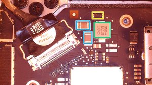
On this image, you can refer to the schematic if you want, but essentially these are the parts in play here. The large component in green is L7701 - an inductor, almost always fails in a way that you can tell. They crack, or have a hole burned in them, etc... This one looks fine, but it should be electrically continuous if it's good
On the other side of that inductor, the backlight driver pumps an output into that line that switches on and off, and feeds it through D7701- a diode (the part outlined in yellow), which is like a 1 way valve for electricity. As a rudimentary test I would check resistance across this in both directions. It should test as OL (over limit/open line) in one direction, but give some resistance measure in the other. It's not the best test, but it will do here.
On the other side of the diode, a branch of that line goes to the big capacitors, in blue here, (and some small ones), which I doubt are bad because they would likely fail as short to ground and you wouldn't be getting 8 volts, and you'd be getting a helluva lot of heat.
A second branch of the post diode line loops back around around to the backlight driver to give it feedback on the voltage present there. Which is how it adjusts brightness. it changes the frequency of how often the switching lines power on and off to increase or decrease voltage, therefore decreasing or increasing the brightness of the back light. (Cool, right?)
This is where I think your issue is. Unfortunately it's a bit of a bear to test. The trace (read: wire within a circuit board) for this feedback line goes to the test point between U7701 and D7701, through to the other side of the board to the feedback pin on the backlight driver. This trace can burn out, or become damaged. To fix it, you'll need to run a jumper wire from the test point around the board, to the feedback pin on the backlight driver since that's the only 2 places that line runs. I am not sure how solder savvy you are, but it's not super difficult if you are versed in soldering small bits. Otherwise it might be best left to a shop that does these kinds of things.
Был ли этот ответ полезен?
Проголосовали
Отменить
Счет
2
Отмена
Прокрутите эту тему, чтобы найти подходящее место для этого комментария. Затем нажмите "Прикрепить комментарий к этому сообщению", чтобы переместить его.


8 Комментариев
@std_phl what voltage do you get on pin 3 or pin 4 on your LCD connector? It will give you at least a hint that if it is high, check your connector to the display etc. If it is around 25 V and higher you know your boost circuit is working so again the error is past the contact on the connector/cable/LCD (I know it's new but still needs to be mentioned). If it is around the 8V you measured on the fuse you know it is not getting boosted, could be an issue with it either not being enabled or a bad component in between. If it is less than that, you know there is an issue with the boost circuitry.
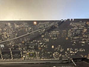
Post some good pictures of your logic board and the LCD connector and the rest of the board. Yes, both sides needed because components for this circuitry are all over the place :-) with your QUESTION. That way people can see what you see and can hopefully guide you a little further.
Adding images to an existing question
из oldturkey03
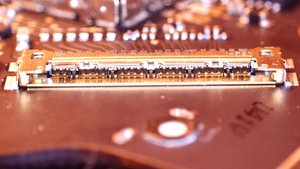
Thank you @oldturkey03 for the info and sorry for the delay. I've added some pictures above, some taken with a phone some taken with a cheapo digital microscope. Hopefully they are informative despite the diverse white points.
I'm sorry that I don't know which pin is which in at the LVDS connector. With my microscope guiding careful placement of a sewing needle in an alligator clip on the voltmeter, I saw just 3 millivolts on the 3rd and 4rth pin from the hinge (in the upper right of the first image after "close-up of LVDS connector"), and about 190 mV on the 3rd and 4th pin from the other end (lower left, closer to USB port). The tiny tip of the needle and my janky set-up surely dropped some voltage, but with the same set-up I saw 2.7 volts at the test point for backlight enable (see below).
из Standard Phillips
Thank you @oldturkey03 for the customized pin numbering guide based on my picture; that was very generous of you. And thanks in advance for your continued patience; the time windows when I can safely work on exposed hardware do not come every day.
I've remeasured the voltage at pins 3 and 4, this time with the computer not asleep and with the LVDS connector plugged in. Now I see 8.42V on pins 3 and 4 (not the 3mV I reported above).
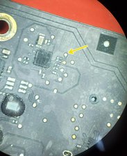
At the C8317 you labeled I see 8.43V. On the other side of the same component (closer to the viewer on the same pic you annotated) I see just 0.1 mV.
Do you have any thoughts on the pics of the fuzzy backlight driver that I took at @flannelist 's suggestion?
из Standard Phillips
@std_phl looks fuzzy but not corrosion. It is always good to clean it with some isopropyl alcohol and a soft brush. The voltage on your points show that your boost circuit is not working.. Now it's a hen and egg thing. Is it because it is not enabled or because it has failed? Your 2.7V should be good to turn it on. So, use the schematic for the backlight and trace your components measuring the voltage. Let's see what @flannelist thinks.
из oldturkey03
Thanks @oldturkey03 for the info; you *might* be over-estimating my abilities. Can you give me a tip for how to start the process of using the schematic you provided to the trace the components? Or, are there any diagrams or annotated photos of the logic board, with some more of the components labeled, that I could use for guidance?
And yes, looking forward to hearing @flannelist 's thoughts.
из Standard Phillips
Показать ещё 3 комментариев