Перейти к основному содержанию

Портативная игровая консоль производства Valve, выпущенная 25 февраля 2022 года.

256вопросов Показать все

Need help Identifying Resistor value

Block Image

Hello. Long story short, doing a repair on a steamdeck that wasn't charging at all. Voltage and amp readings were fluctuating before switching off and on with amp meter.

Anyway, found the current sense R010 and a little resistor north to it causing shorts on some nearby caps on the max chip. Took them off but lost the smaller resistor. Does anyone know the value of it and it's corresponding size please? I checked the MAX77960/MAX77961 docs and the CSIN & CSINP pins point to a 10mΩ 1206 but that is way to big for it to be the right one (too big dimensions wise). Any help would be appreciated and its an LCD model. Thanking all the kind hearts out there. :)

Ответ на этот вопрос У меня та же проблема

Это хороший вопрос?

Оценка 1
Добавить комментарий

2 Ответов

Наиболее полезный ответ

We might also need to know your board revision because there are a few in the wild on these and the layout in your pictures does not match the one from the iFixit teardown. Although, chances are the values on the various boards are the same, just in different locations.

All that being said, here's what I have gathered from the datasheet the 1206 resistor is the current sense one. because that's the correct package size, although R010 I think is .01 ohm, not 10. Unless I am misremembering.

There is a reference for RCSINP which is an 0402 package, which looks more accurate. But if you look at the diagram, on page 80, where I expect you got those values, there are 2 resistors on either side of the current sense one which go back to those pins, they just don't give values for it, other than package size. I realize that doesn't help much, but if it were me, I might correlate the other resistor, since it's basically just comparing values on either side of the current sense resistor.

Measure this resistor on the other side of the current sense one. I tried to markup the picture, but it doesn't allow markup on images that small. It's the one right in the lower left of the battery connector in your image. .

Был ли этот ответ полезен?

Оценка 2

8 Комментариев:

Board Rev F. It is disimiliar to the ones from the diagram on your article but similiar enough. So the 10MΩ 1206 on the datasheet is the current sense one which definitley went bad in my case but I thought R010 meant 0.01Ω!? But the datasheet says 10MΩ. The one that was shorting the circuit from my board read R010 but It definitley makes sense from a dimensions point view so atleast I can order that one because I was worried about the sizing of it. Some sites selling them say 0.01Ω but on the specifications they write 10MΩ!?

You're right, the resistor which looks to be in parrallel (pg 79/80) under the current sense one is the best way to go about it. And they are both definitley 0402. 99% sure about that. I did a continuity and found those two resistors (the one directly north of the current sense resistors upper pad and the one directly east of the upper pad) so can confirm they are the ones in question.

Awesome stuff and thank you so much. You are indeed a kind heart & all the best. God bless!

из

@takezosan oh it says 10mΩ which is milliohm or .001Ω. Which is much closer to your .01Ω.

Mega ohm is in fact MΩ, which would be a huge difference, but I overlooked the m altogether.

Either way hopefully that got you on the right track. Let us know what you find! That way the next person can also benefit from this wisdom.

из

Oh look at that! LOL, it does say mΩ. Okay so update, the replacement R010 came (was little bigger in size but should be fine to sit on the pads) but still waiting for the replacement 10Ω 0402 ones to arrive. Will update as soon as they arrive and have been fitted. I'm 99% sure that it should fix things because I read that current sense fault can cause the IC controller to not know how much power to relay to the CPU. It has no idea hence the initial symptoms of fluctuating current and volts and the charger switching on and then trying again...and then again in that cycle. Thanks again and will let you guys know.

(I did find a 20Ω resistor on a random donor board but I wasn't sure enough to use it because it would be in parallel to a 10Ω connected directly to a current sense so I don't know for sure how it would impact the charge cycle. Probably would give less amperage or slower charge or something else but I don't want to take that risk.)

из

@flannelist No, a mΩ is 0.001Ω, so 10mΩ is 0.01Ω

and m = 0.001, M = 1,000,000

из

@ruggb Oh you're right. That was what, I originally wrote and then second guessed because I don't metric like I used to. Then google lied to me

.001 would be one thousandth. So yes 1 milli ohm. Duh.

Thanks for keeping me in check.

из

Показать 3 больше комментариев

Добавить комментарий

Finally! So from my last comment on @flannelist helpful answer, I headed towards that MAX77958 chip. Took it off and measured VBUS (pin A6/top right) and that pin was shorting to ground. And it had that same 7ohm resitance to it. So now what!? I found a capacitor near the usb-c port that was also shorting. It was a 1206 or 0805 capacitor and I think taking it off and measuring it, it was 10uF (can't remember too well to be sure of that value). Shorting, just like the others with the same ohmic value. So I felt like I'm getting closer and then I follow further up that shorted capactiors's track and it lead to a diode (D51). That was shorting, with the same ohmic value. Took it off and no difference. From here I should have realised the answer but like a dummy I went for the ITE controller chip and just took it off and wasted my time. I was shooting in the dark now.

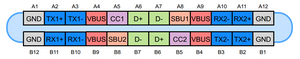
I didn't know what to do so I went invasive and got the PSU and thermal camera out. Starting with 1v/1a at the non-grounding pad of the diode and also the capacitor on the back of the board in relation to the MAX77958 (mentioned before in the comments part of the best answer). I double checked the APU to be sure it wasn't getting the voltage and it wasn't lighting up so I turned it up to 3v/1a and then eventually to 3v/1.5a. Nothing was showing up where I thought it would. Nothing around the MAX77958 or the MAX77961 (and those chips are out of circuit). Until I saw the middle and the right side of the USB-C pins light up/heat up and heat down when I switched the voltage on and off. Checked the thermals/temps and it was rising a couple of degrees C when I did switched the PSU on and off. So now I figure, let me check the the pins on the USB-C!? The first and last pins are ground and every other pin was fine but the fourth pins from either side were shorting. Quick lookup at the USB-C schmatics

Block Image

Aaaaaand those are the VBUS pins. BINGO!!!! It all made sense now and the moment of truth was removing the USB-C connector and checking if the shorts dissapeared. So I Did that and praise the Lord, they were all gone!!! Now just waiting for a replacement USB-C connector to arrive and install it. 🎉

I did find this repair quite deceptive and tricky but the common denominator were those ~7 ohmic values always appearing on that charging line and the VBUS always coming up in the picture too. I would never have guessed that a faulty USB-C connector could be an issue like this as most of the time its quite robust and if anything, chips or caps fail or even the current sense resistor that I initally thought showed that it was the problem. I wanted to inspect the USB-C connector but it fell off my tweezers, heard it bounce and then it vanished into some other dimension, it seems. If it turns up from holiday one day, I will have a look at it more closely just to see what it looks like for burns on the inner row of pins or anything out of the ordinary that could have caused this connector to fail.

But a lesson for me here is, look for what is happening and showing signs of the problem and not for what you want to happen or want the problem to be.Will follow up in a comment somewhere when it hopefully is put back together and hopefully charging and exchanging data through the port and ofcourse, turning on.

Thanking you Kind hearts @flannelist and @ruggb for your input into this problem.

PS. Why did I take off the ITE chip. Now I have to reball it!!!!

Был ли этот ответ полезен?

Оценка 1

1 Комментарий:

Thank you thank you thank for this detailed update. I cannot tell you how much I love everything about this.

I had a feeling the resistors were just clues since they would usually fail as open rather than short. I suspected you might be on the right track with the MAX chip since that could go short to ground internally. But this just goes to show how easy it is to follow your brain into a rabbit hole because it's the more fun fix. And don't we all want a good mystery? Way more rewarding at the end.

Every good technician and IT professional I know has had one (or many) of these repairs. And for what it's worth, they are sometimes my favorite even though you usually want to kick yourself for missing something that might have been obvious. I'm definitely a learn stuff the hard way tech at times. So I relate.

Hopefully the ITE chip wasn't too much hassle. I have no idea how many balls are under there, so hopefully not too many even though its a sizable IC.

Double hoping the new port fixes it.

из

Добавить комментарий

Добавьте свой ответ

Takezo-san будет вечно благодарен.
Просмотр статистики:

За последние 24часов: 4

За последние 7 дней: 25

За последние 30 дней: 67

За всё время: 67