Введение
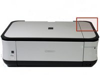
Use this guide to replace a broken data port in your Canon Pixma MP480 Printer. Replacing your data port will help you regain your USB and card readers.
The data port is a piece of hardware that is responsible for transmitting and receiving memory from your device to your printer. With a broken data port, flash drives and/or memory cards cannot connect and retrieve data from your printer to your laptop or device. Your printer's front data port (USB and Memory Card Reader) may need replacement if you plug in a flash drive or memory card reader and the printer does not recognize it.
Before using this guide, consult and review the troubleshooting page. Oftentimes, issues can be solved without replacing the data port.
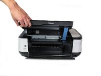
Before beginning, ensure that your printer is powered off and disconnected from any external power source.
Выберете то, что вам нужно
-
-
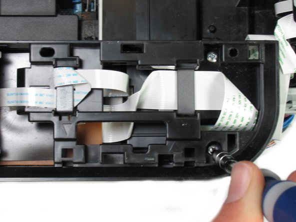
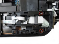
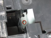
Remove the two 7.9 mm screws using a Phillips #1 screwdriver.
 Спросите у FixBot
-
-
-
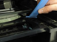
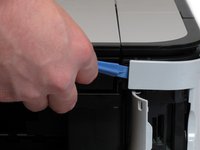
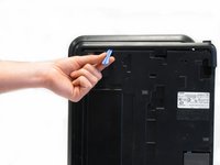
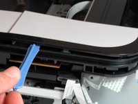
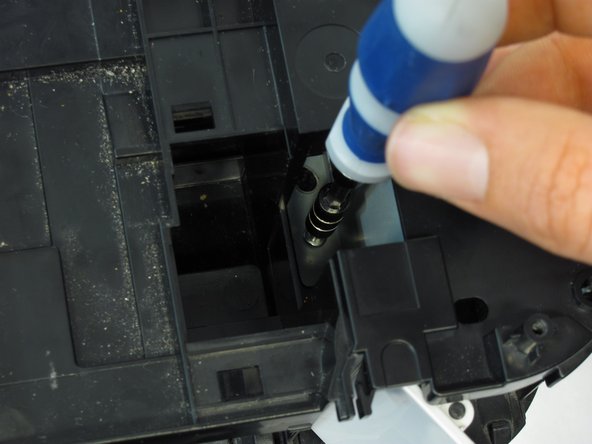
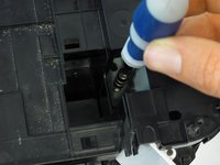
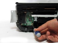
Remove the blue lever from its slot by pushing it back and twisting clockwise.
-
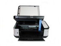
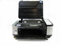
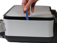
Close the scanner compartment and cover.
-
-
-
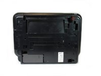
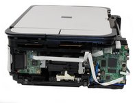
Flip the printer over so that the bottom of the printer is facing you.
-
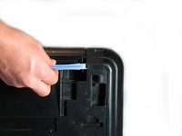
Use the plastic opening tool to remove the corner of the side panel from the plastic pin.
-
-
-
Use the plastic opening tool to loosen the side panel from the bottom of the printer.
-
-
-
Using the plastic opening tool, pry off the top cover of the LCD assembly.
-
-
-
After removing the top cover of the LCD assembly, remove the LCD using the plastic opening tool.
-
-
-
-
Using the plastic opening tool, gently pry under the button cover to remove it from its fixture.
-
-
-
Remove the five 7.7 mm screws using a Phillips #1 screwdriver.
-
-
-
Using the plastic opening tool, gently pry around the cover behind the LCD screen to remove it from its fixture.
-
-
-
Remove the two 7.8 mm screws using a Phillips #1 screwdriver.
-
-
-
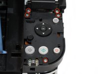
Use the plastic opening tool to pry off the plastic button assembly.
-
-
-
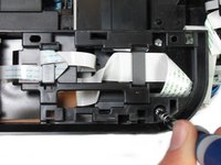
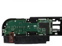
Remove the ribbon cable connected to the backside of the plastic button assembly.
-
-
-
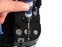
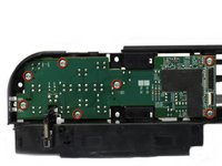
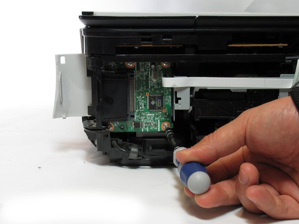
Remove the seven 8.7 mm screws using the Phillips #1 screwdriver.
-
-
-
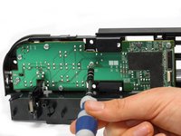
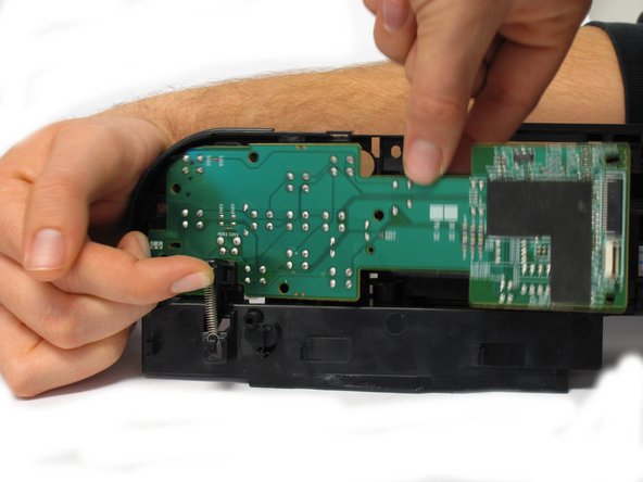
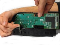
Locate the spring that holds the PCB in place on the bottom left of the plastic button assembly.
-
Gently lift the spring and pull the board out of its plastic button assembly.
-
-
-
Remove the 7.5 mm screw using the Phillips #1 screwdriver.
-
-
-
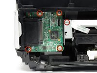
Remove the five 3.5 mm screws using the Phillips #1 screwdriver.
-
-
-
Pull the plastic inserts out of the holes in the top and bottom.
-
-
-
Remove the board from the printer by pulling the board towards the back of the printer.
-


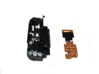


To reassemble your device, follow these instructions in reverse order.
Команда

Cal Poly, Team 19-41, Regan Winter 2013 Участник Cal Poly, Team 19-41, Regan Winter 2013
CPSU-REGAN-W13S19G41
4 членов
Автор 6 руководств