Эта версия возможно содержит некорректные исправления. Переключить на последнюю проверенную версию.
Выберете то, что вам нужно
-
Этот шаг не переведен. Помогите перевести
КупитьИнструмент, используемый на этом этапе:P5 Pentalobe Screwdriver Retina MacBook Pro and Air$5.99-
Use a P5 Pentalobe driver to remove ten screws securing the lower case, of the following lengths:
-
Two 9 mm screws
-
Eight 2.6 mm screws
-
-
Этот шаг не переведен. Помогите перевести
-
Wedge your fingers between the display and the lower case and pull upward to pop the lower case off the Air.
-
Remove the lower case and set it aside.
-
-
Этот шаг не переведен. Помогите перевести
-
Grab the clear plastic pull tab attached to the battery connector and pull it toward the front edge of the Air to disconnect the battery from the logic board.
-
-
Этот шаг не переведен. Помогите перевести
-
Use the flat end of a spudger to pry the I/O board cable connector upward out of its socket on the I/O board.
-
-
Этот шаг не переведен. Помогите перевести
-
Carefully peel the I/O board cable from the top of the fan.
-
-
Этот шаг не переведен. Помогите перевести
-
While gently pulling the I/O board cable upward near its connection to the logic board, use the tip of a spudger to pry upward on alternating sides of the connector to help "walk" it out of its socket.
-
Remove the I/O board cable.
-
-
Этот шаг не переведен. Помогите перевести
-
Use the tip of a spudger to carefully flip up the retaining flap on the fan cable ZIF socket.
-
-
-
Этот шаг не переведен. Помогите перевести
-
Peel the rubber gasket off the adhesive on the top of the fan.
-
-
Этот шаг не переведен. Помогите перевести
-
Remove the following three screws securing the fan to the upper case:
-
One 3.6 mm T5 Torx screw
-
One 2.7 mm T5 Torx screw
-
One 3.6 mm T5 Torx screw with a short head
-
-
Этот шаг не переведен. Помогите перевести
-
Lift the fan out of the upper case and carefully pull the fan ribbon cable out of its socket as you remove it from the Air.
-
-
Этот шаг не переведен. Помогите перевести
-
Disconnect the I/O board by pulling the power cable away from its socket on the logic board.
-
-
Этот шаг не переведен. Помогите перевести
-
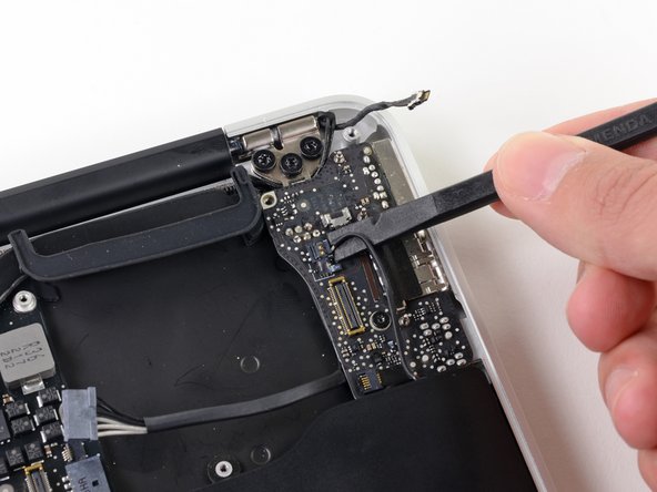
Pull the camera cable parallel to the face of the I/O board toward the hinge of the Air to disconnect it from its socket, using the tip of a spudger to help push the connector out of its socket.
-
-
Этот шаг не переведен. Помогите перевести
-
Use the flat end of a spudger to pry the left speaker cable connector up and out of its socket on the I/O board.
-
-
Этот шаг не переведен. Помогите перевести
-
Use the tip of a spudger to flip up the retaining flap securing the microphone ribbon cable to the I/O board.
-
Use the tip of a spudger to remove the volume button ribbon cable from its ZIF connector on the I/O board.
-
-
Этот шаг не переведен. Помогите перевести
-
Remove the single 4.0 mm T5 Torx screw securing the I/O board to the upper case.
-
-
Этот шаг не переведен. Помогите перевести
-
Carefully lift the I/O board from its edge nearest the logic board and remove it from the upper case.
-
-
Этот шаг не переведен. Помогите перевести
-
Remove the two 4.9 mm T8 Torx screws securing the antenna cable retainer on the left display hinge to the upper case.
-
-
Этот шаг не переведен. Помогите перевести
-
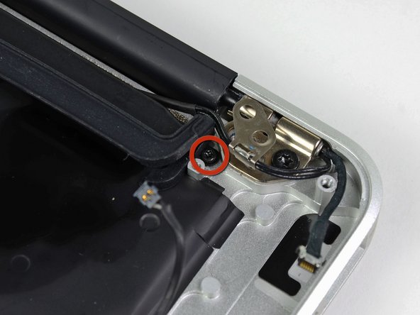
Push the antenna cable retainer out of the way and remove the 3 mm T5 Torx screw securing the end of the heat sink to the upper case.
-
-
Этот шаг не переведен. Помогите перевести
-
Remove the four 2.5 mm T5 Torx screws securing the heat sink to the logic board.
-


Отменить: Я не выполнил это руководство.
24 участников успешно повторили данное руководство.

5 Комментариев
I just swapped out a snapped heatsink & faulty fan, now the Macbook Air fan is on full within 20 seconds of boot & the mouse is lagging like crazy.
I’ve been assembling & repairing computers for years, so know how to apply thermal paste properly, so I’m wondering if I’ve missed something crucial here. Anybody else had issues after replacing the heatsink?
Replaced the 6 year old dried up thermal paste with liquid metal, worked like a charm!
Hello Gabriel, did you only replace the thermal paste? Or did you install a new heat sink too? My Macbook Air is overheating and shutting down. It has gotten worse over time. I am wondering if just cleaning and replacing the thermal paste will work? What do you think?
Thank you!
Chip -
On my Air the fans were running a lot, but no overheat shutdowns.
I replaced only the thermal paste and after that that the fans rarely ever turned on.
Can I do this without removing the fan and input board? It is possible to loosen the most right screw holding heatsink, I tried. So why do i need to remove so many other things?