Введение
Use this guide to replace the MagSafe DC-In board.
Выберете то, что вам нужно
-
-
Remove the following ten screws securing the lower case to the upper case:
-
Two 2.3 mm P5 Pentalobe screws
-
Eight 3.0 mm P5 Pentalobe screws
-
-
-
Wedge your fingers between the upper case and the lower case.
-
Gently pull the lower case away from the upper case.
-
Remove the lower case and set it aside.
-
-
-
The lower case is connected to the upper case at the center, with two plastic clips.
-
-
-
Remove the plastic cover adhered to the battery contact board.
-
-
-
Remove the following screws securing the battery connector board to the logic board:
-
Two 2.8 mm T6 Torx screws
-
One 7.0 mm T6 Torx shouldered screw
-
-
-
Use tweezers to remove the small plastic cover located near the bottom right of the battery connector board.
when doing this with metal tweezers as instructed in the video, it was difficult to get off and apparently while i was trying to do it, the tweezers went too far under and i believe made contact with the screw underneath? there was a zzz noise, an orange flicker and a little stream of smoke that came out. i freaked out and put everything back together to see if the laptop even still worked, it turned on and everything but died right away (i drained it before doing the repair anyway, so i was surprised it turned on at all).
i finished the battery repair and did several other things while in there. i have charged it all the way as recommended and will use it later on to see how everything is, im hoping that it’s a okay, but could someone explain to me what happened and the possible consequences?
-
-
-
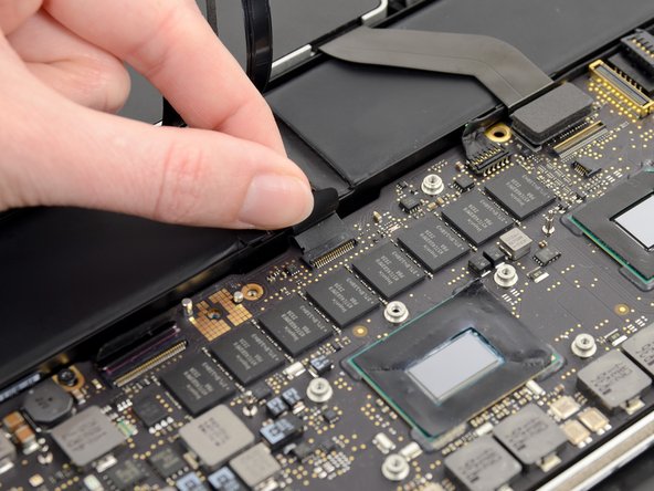
Remove the wide head 6.4 mm T6 Torx screw securing the battery connector to the logic board assembly.
-
-
-
Carefully lift the battery connector board up off the logic board.
-
It is recommended to bend the battery cables just slightly, to keep the board suspended up above the logic board and out of the way.
-
-
-
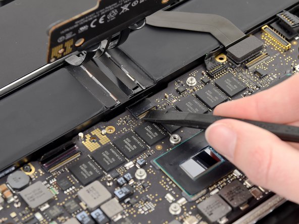
Grasp the Interposer with tweezers.
-
Lift the Interposer off the logic board and remove it.
you must lift it absolutely vertically, or it fouls against the locator pin in the corner- you can easily get the impression that it won’t come over the end of this pin- almost like it’s rivetted in. it isn’t. get a good grip on it with the tweezers in the centre hole & one of the sides, & lift it STRAIGHT up.
I would recommend to use plastic tweezers in order to reduce risk of damage.
Second that. If you have thin heat shrink tubing, form some over the tweezer tips. If the tubing is thin and small enough in diameter you’ll see the serrations of the tweezer tips.
wat is the model this SSD
-
-
-
Remove the following screws securing the heat sink to the logic board assembly:
-
One 2.4 mm Phillips #00 screw
-
One 3.4 mm T5 Torx screw
-
Four 2.7 mm T5 Torx screws
Hi,
found 4 rubber spacers on the 4 2,5mm screws
-
-
-
Use the flat end of a spudger to pry the right side of the I/O board data cable connector up off its socket on the I/O board.
-
-
-
-
Wedge the flat end of a spudger beneath the left side of the I/O board data cable connector.
-
Gently twist the spudger to disconnect the I/O board data cable connector from its socket on the logic board.
-
-
-
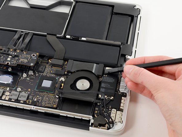
Use the tip of a spudger to flip up the retaining flap on the right fan ribbon cable ZIF socket.
-
Pull the right fan ribbon cable straight out of its socket on the logic board.
Hey! You skipped a step!
What about the cable (don't know what it does) that runs right across the fan, interfering with pulling the fan out.
It's still in place in Step 14, but here in Step 15 it's magically removed itself, and can be seen resting luxuriously on top of the Airport card.
How do we get that outta there?
Like @victorgav mention, Just need a step before this one, which is to remove the cable that goes across the top of the fan.
Thanks for bringing this up! It looks like the guide was missing the iSight cable disconnection steps. I’ve added the missing steps.
-
-
-
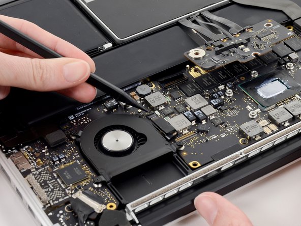
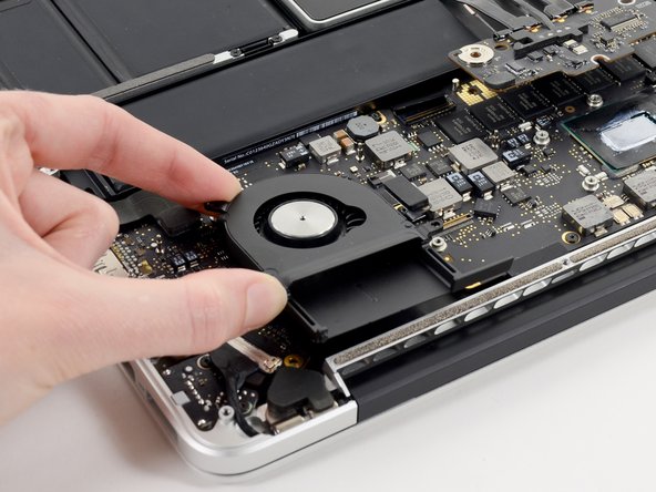
Remove the three 3.1 mm T5 Torx screws securing the right fan to the logic board assembly.
-
-
-
Use the tip of a spudger to flip up the retaining flap on the left fan ribbon cable ZIF socket.
-
-
-
Remove the three 3.1 mm T5 Torx screws securing the left fan to the logic board assembly.
-
-
-
Use the tip of a spudger to push the edges of the I/O board connector straight out of its socket on the logic board.
-
-
-
Wedge the flat end of a spudger underneath the keyboard backlight connector and the logic board.
-
Gently twist the flat end of a spudger upwards to pry the keyboard backlight connector up off its socket on the logic board.
-
-
-
Grab the black pull tab secured to the display data cable lock and rotate it toward the DC-In side of the computer.
-
Pull the display data cable straight out of its socket on the logic board.
-
-
-
Use the tip of a spudger to flip up the retaining flap on the microphone ribbon cable ZIF socket.
-
Grasp the plastic pull tab and pull the microphone ribbon cable out of its socket.
-
-
-
Use the flat edge of a spudger to flip up the retaining flap on the keyboard ribbon cable ZIF socket.
-
Grasp the plastic pull tab and pull the keyboard ribbon cable out of its socket.
-
-
-
Repeat the previous procedure to disconnect the Trackpad ribbon cable from its socket on the logic board.
I discovered that if the trackpad cable is damaged the keyboard will not work. I replaced the trackpad cable which had two damaged Ribbon pens. Once TP cable was replaced the keyboard also worked!
-
-
-
Wedge the flat end of a spudger beneath the right speaker cable connector.
-
Gently pry the right speaker cable connector up off from its socket on the logic board.
-
-
-
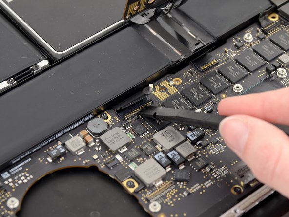
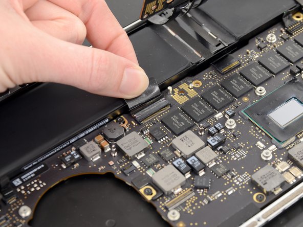
Use the flat end of a spudger to pry the SSD cable connector up off its socket on the logic board.
-
-
-
Wedge the tip of a spudger beneath the left speaker cable connector.
-
Gently pry the left speaker cable connector up off from its socket on the logic board.
-
-
-
Remove the nine 3.3 mm T5 Torx screws securing the logic board and MagSafe DC-in board to the upper case.
-
-
-
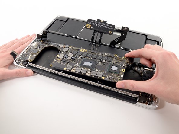
Carefully grasp the corner of the logic board (opposite of the I/O ports) and lift the logic board out of the upper case.
When re-installing the Logic board, be careful not to trap any of ZIF cables under the board.
You’ll need to tilt the board up from the end away from the DC-IN board in order to get the IO connectors inserted all the way. Be careful with the little fingers on top of the IO connectors.
I had previously replaced the battery with the Newer Tech battery. The battery cable is not as flexible as the original battery, making the removal and insertion of the trackpad cable difficult.
-
-
-
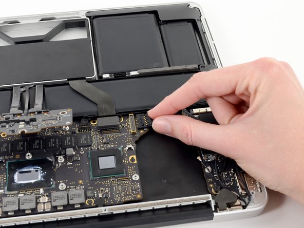
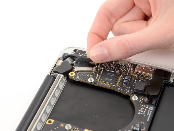
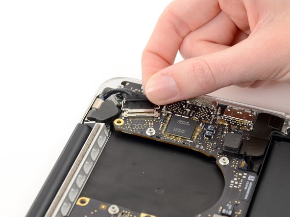
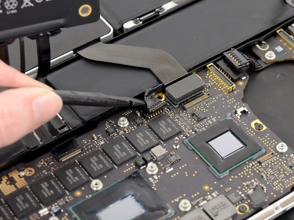
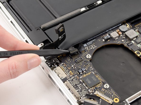
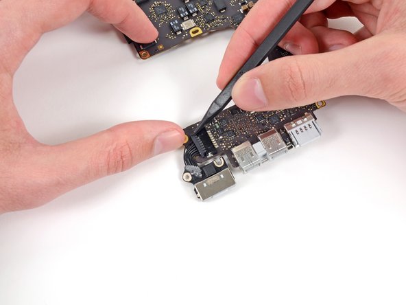
Gently push the edges of the MagSafe cable connector away from its socket on the logic board.
-
-
-
Pull the MagSafe cable connector straight out of its socket on the logic board.
-


To reassemble your device, follow these instructions in reverse order.
To reassemble your device, follow these instructions in reverse order.
Отменить: Я не выполнил это руководство.
14 участников успешно повторили данное руководство.

Один комментарий
Great tutorial. I would add two comments. Firstly between steps 14 and 15 there is a cable that needs to be unconnected (see other tutorials where it is detailed) - it needs to be "walked" out, and you ned to remember to reconnect this. Secondly when putting the logic board back in be sure not to trap any of the connectors underneath it. It is a real struggle! I ended up undoing the 6 screws that hold the main battery assembly in and lifting this slightly to give me space and allow me to reinsert the ribbon cables on that side of the board. The reason I needed to disassemble my laptop was that it kept going into sleep mode, sometimes every few seconds. Apple wanted to charge £550 to fix it. I found the problem was with the micro-switch that detects if the lid is closed (it would work fine in clamshell mode). Switch is between the thunder port and USB sockets. Sprayed with contact cleaner, isopropyl and antistatic spray and dried with hairdryer, been working a treat since! Cost of a pentalobe driver!
If don’t have one of those neat project mats, then you can use small pieces of flattened blu-tack to hold the screws. If you arrange them in the shape of your mac book cover, and put the screws down methodically, you can get a one-to-one mapping of the screws to the correct screw holes.
Toby Thurston - Ответить
Or you can use an ice tray where you put the screws and the parts in separate bays in the same order as they come in the instructions.
timofej.se -
This is great! I used a small magnetic white board, and wrote on it to identify the parts as I went. This whole process, from the fast shipment to the great instructions to the complete, high quality, tool kit has been great. I’m typing this comment on my resurrected laptop. Thank you! Sue
Susan Greer - Ответить
It would be a good idea if people recorded in the comments which screws go where so that, if someone lost their screw positions, they could recover them from the comments.
Raymond Shpeley - Ответить