Введение
Replace the I/O board, which includes the SD card slot, the HDMI port and the right USB port.
This guide requires the removal of the heat sink. Don't forget to follow our thermal paste application guide before you reinstall your heat sink.
Выберете то, что вам нужно
-
Инструмент, используемый на этом этапе:Magnetic Project Mat$16.96
-
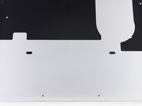
Remove the following ten screws securing the lower case to the upper case:
-
Two 2.3 mm P5 Pentalobe screws
-
Eight 3.0 mm P5 Pentalobe screws
-
-
-
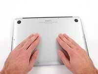
Wedge your fingers between the upper case and the lower case.
-
Gently pull the lower case away from the upper case to remove it.
-
-
-
Use the flat end of a spudger to lift the battery connector straight up out of its socket on the logic board.
-
-
-
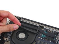
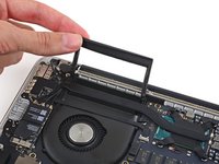
Carefully remove the rubber fan bumper from the edge of the heat sink.
-
-
-
Use the flat end of a spudger to peel the four foam stickers off of the heat sink screws.
-
-
-
-
Remove the following screws securing the heat sink to the logic board:
-
Four 2.6 mm T5 screws
-
One 2.4 mm Phillips #000 screw
-
-
-
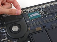
Use the tip of a spudger to push on either side of the the iSight camera cable connector to walk it out of its socket on the logic board.
-
-
-
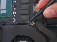
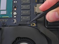
Use the tip of a spudger to flip the tab on the fan's ZIF connector.
-
Carefully pull the fan cable straight out of its socket.
-
-
-
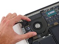
Remove the following screws securing the fan to the upper case:
-
One 5.0 mm T5 Torx screw
-
Two 3.6 mm T5 Torx screws
-
-
-
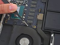
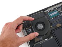
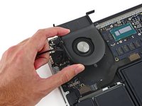
Lift the end of the fan closest to the display hinge and remove the fan from the upper case.
-
-
-
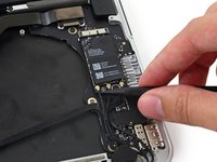
Insert the tip of a spudger under each of the antenna cables near their connectors and pry up to disconnect them from the AirPort board.
-
Connect the long-sleeved cable to the center socket.
-
The short-sleeved cable connects next to the screw.
-
The remaining cable has no sleeve, and connects in the last empty socket, next to the fan.
-
-
-
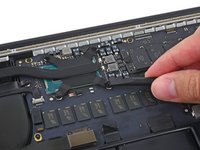
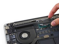
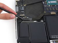
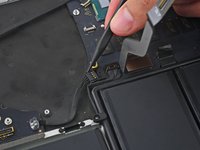
Remove the two 2.1 mm T5 Torx screws securing the I/O board cable bracket.
-
Remove the I/O board cable bracket.
-
-
-
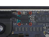
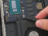
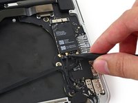
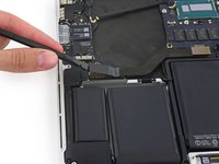
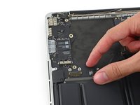
Use the flat end of a spudger to pop the I/O board connector straight up off its socket on the I/O board.
-
Push the I/O board cable up to bend it out of the way.
-
-
-
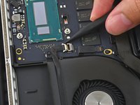
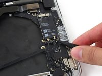
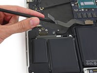
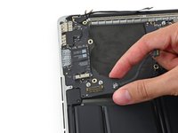
Use the tip of a spudger to push on either side of the I/O board connector to walk it out of its socket on the logic board.
-
-
-
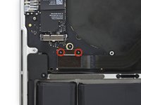
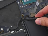
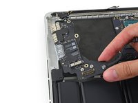
Remove the following screws securing the I/O board to the upper case:
-
One 3.5 mm T8 Torx standoff screw
-
One 3.5 mm T5 Torx screw
-
-
-
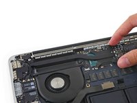
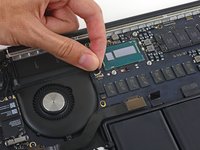
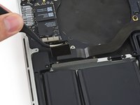
Lift the I/O board cable end of the I/O board and pull toward the logic board to free the ports from the upper case.
-
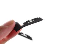
Remove the I/O board.
-
-
-
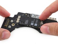
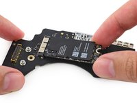
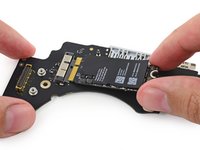
Remove the single 2.7 mm T5 Torx screw securing the AirPort board to the I/O board.
-
-
-
Lift the free end of the AirPort board up slightly and pull it straight out of its socket on the I/O board.
-


To reassemble your device, follow these instructions in reverse order.
Отменить: Я не выполнил это руководство.
20 человек успешно провели ремонт по этому руководству.


1 Комментарий к руководству
Thank you! My Macbook was not starting anymore and I saw that it will boot without the IO board. I got a new part, exchanged it and it is now working flawlessly.