Эта версия возможно содержит некорректные исправления. Переключить на последнюю проверенную версию.
Выберете то, что вам нужно
-
Этот шаг не переведен. Помогите перевести
-
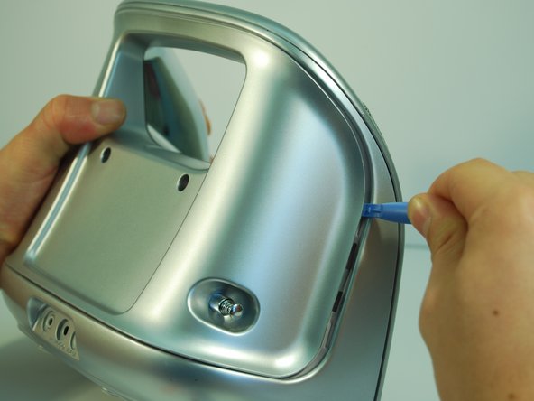
Remove the two plastic screw covers on the back of your Minimove by inserting the flat end of your plastic opening tool between the screw cover and the back panel and prying it out.
-
-
Этот шаг не переведен. Помогите перевести
-
Use a Phillips #1 screwdriver to remove the two 12 mm screws.
-
-
Этот шаг не переведен. Помогите перевести
-
Remove the four grey screw covers by inserting the plastic opening tool underneath the screw covers and rotating around the circumference.
-
-
Этот шаг не переведен. Помогите перевести
-
Remove the two 8 mm screws with a Phillips #1 screwdriver.
-
Remove the two 12 mm screws with a long Phillips #1 screwdriver.
-
-
Этот шаг не переведен. Помогите перевести
-
To remove the back panel, use the plastic opening tool and gently work around the outline of the panel. The outline wraps around the sides and can be spotted at the top back of the device.
-
-
Этот шаг не переведен. Помогите перевести
-
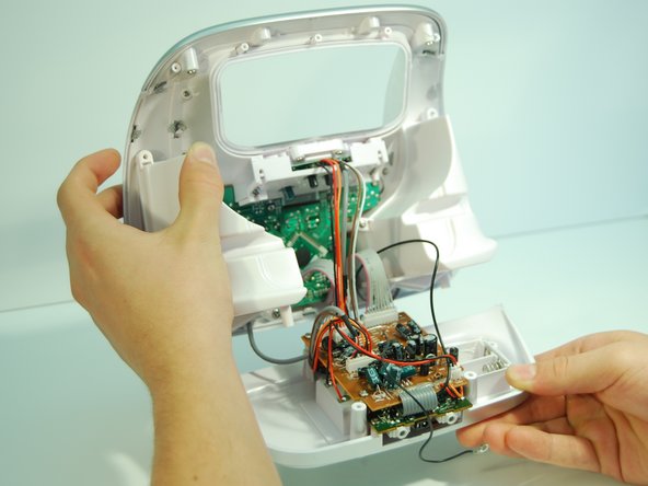
After loosening the panel with the plastic opening tool, use moderate force to pry open the panel with your hands.
-
Carefully pull the panel off.
-
-
-
Этот шаг не переведен. Помогите перевести
-
Use a Phillips #1 screwdriver to detach the wire from the back panel by removing the 8 mm screw connecting the wire to the antenna.
-
-
Этот шаг не переведен. Помогите перевести
-
If desired, the antenna can now be removed by pulling inwards and horizontal to the panel bottom.
-
-
Этот шаг не переведен. Помогите перевести
-
Use the Phillips #1 screwdriver to remove the four 12 mm screws.
-
Remove the five 6 mm screws at the top with the same screwdriver.
-
-
Этот шаг не переведен. Помогите перевести
-
Use a Phillips #1 screwdriver and remove the two vertical 8 mm screws from the top.
-
-
Этот шаг не переведен. Помогите перевести
-
Pry open the inner back panel by inserting the plastic opening tool in the crack at the top corner.
-
Use moderate force to pry it open and take the cover off.
-
-
Этот шаг не переведен. Помогите перевести
-
Remove the bottom panel of the boombox by carefully pulling the panel straight backwards from the boombox until the motherboard and daughterboard are free.
-
-
Этот шаг не переведен. Помогите перевести
-
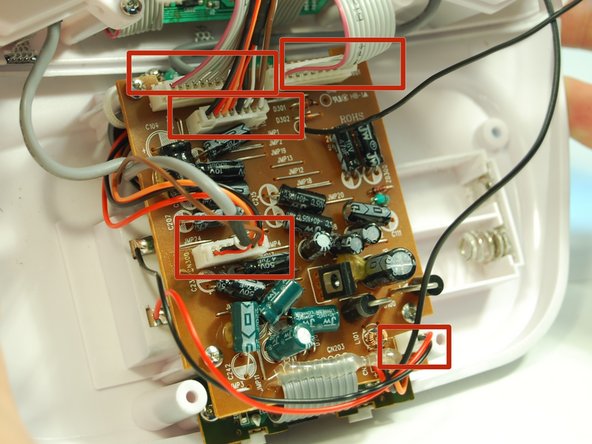
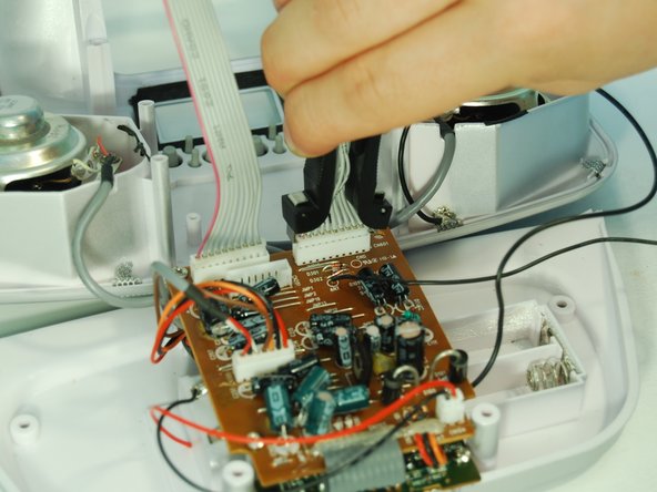
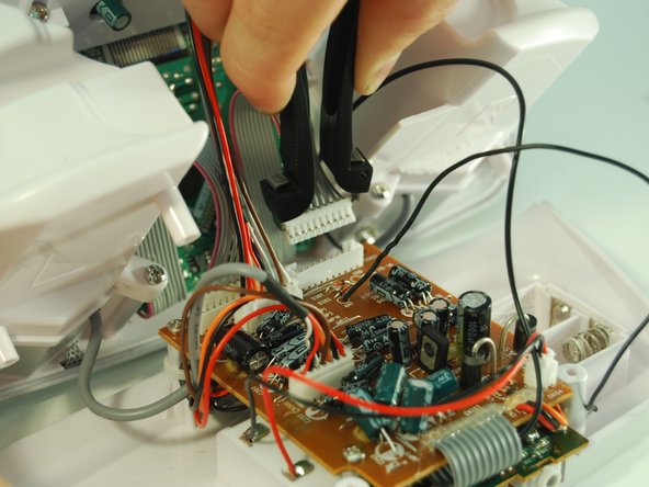
Pull out the 5 white pinhead connectors using an IC (Integrated Circuit) extractor. Pinch the IC extractor just under the top lip of the wire housing.
-
-
Этот шаг не переведен. Помогите перевести
-
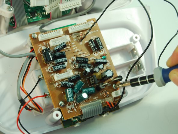
Use the Phillips #1 Screwdriver to remove the three 8 mm screws holding the motherboard in place.
-
-
Этот шаг не переведен. Помогите перевести
-
Detach the smaller green audio port daughterboard by removing the two 8 mm screws with a Phillips #1 screwdriver.
-
-
Этот шаг не переведен. Помогите перевести
-
Locate two wires, one red and one black, located on the left side of the battery pack.
-
-
Этот шаг не переведен. Помогите перевести
-
Heat up the soldering iron to around 600 Fahrenheit / 315 Celsius.
-
Place the tip of the soldering iron on the solder where the wire is connected and melt it until you can detach the wire.
-
Visit the soldering iron guide for more help with desoldering and soldering.
-
-
Этот шаг не переведен. Помогите перевести
-
After detaching the wire, move it away from the device.
-
Use a desoldering pump while the solder is still liquid to remove excess solder.
-


Отменить: Я не выполнил это руководство.
3 участников успешно повторили данное руководство.

Команда

Cal Poly, Team 2-9, Amido Winter 2014 Участник Cal Poly, Team 2-9, Amido Winter 2014
CPSU-AMIDO-W14S2G9
5 членов
Автор 6 руководств