Введение
Use this guide to remove every component from the rear case of your iPhone 5.
Выберете то, что вам нужно
Видеообзор
-
-
Lay overlapping strips of clear packing tape over the iPhone's display until the whole face is covered.
 Спросите у FixBot
-
-
-
Power off your iPhone before beginning disassembly.
-
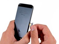
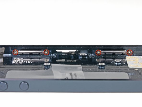
Remove the two 3.6 mm Pentalobe screws next to the Lightning connector.
-
-
-
Regardless of the tool you use, you need to be sure you pull up the entire display.
-
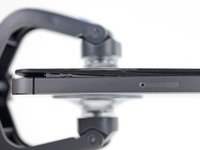
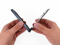
If the glass begins to separate from the plastic, as shown in the first image, slide a plastic opening tool between the plastic frame and the metal phone body to pry the metal clips out of the case.
-
-
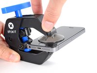
Инструмент, используемый на этом этапе:Clampy - Anti-Clamp$24.95
-
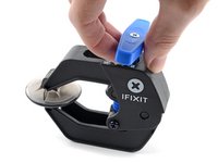
Pull the blue handle backwards to unlock the Anti-Clamp's arms.
-
Slide the arms over either the left or right edge of your iPhone.
-
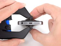
Position the suction cups near the bottom edge of the iPhone just above the home button—one on the front, and one on the back.
-
Squeeze the cups together to apply suction to the desired area.
-
-
-
Pull the blue handle forwards to lock the arms.
-
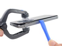
Turn the handle clockwise 360 degrees or until the cups start to stretch.
-
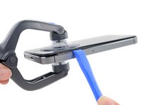
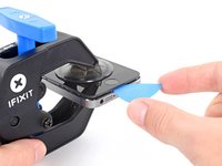
Insert an opening pick under the screen when the Anti-Clamp creates a large enough gap.
-
Skip the next two steps.
-
-
-
Press a suction cup onto the screen, just above the home button.
-
-
-
While holding the iPhone down with one hand, pull up on the suction cup to slightly separate the front panel assembly from the rear case.
-
With a plastic opening tool, begin to gently pry the rear case down, away from the screen, while you pull up with the suction cup.
-
-
-
Continue to pry up around the sides of the front panel assembly, detaching the clips along the left and right side.
-
-
-
Once the clips have been released on the bottom and sides of the front panel assembly, pull the bottom of the assembly away from the rear case.
-
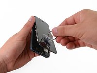
Open the display to about a 90º angle, and lean it against something to keep it propped up while you're working on the phone.
-
Add a rubber band to keep the display securely in place while you work. This prevents undue strain on the display cables.
-
-
-
Remove the following two screws securing the metal battery connector bracket to the logic board:
-
One 1.8 mm Phillips screw
-
One 1.6 mm Phillips screw
-
-
-
Remove the metal battery connector bracket from the iPhone.
-
-
-
Use a plastic opening tool to gently pry the battery connector up from its socket on the logic board.
-
-
-
Remove the following screws securing the front panel assembly cable bracket to the logic board:
-
Two 1.2 mm Phillips screws
-
One 1.6 mm Phillips screw
-
-
-
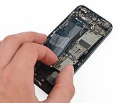
Lift the display cable bracket toward the battery to unhook it, and remove it from the iPhone.
-
-
-
Use a plastic opening tool or a fingernail to disconnect the three front panel assembly cables:
-
Front-facing camera and sensor cable
-
LCD cable
-
Digitizer cable
-
-
-
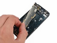
Remove the front panel assembly from the rear case.
-
-
-
-
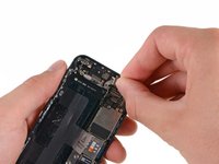
Use the exposed clear plastic pull tab to peel the battery off the adhesive securing it to the iPhone.
-
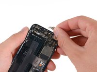
Wait about one minute for the alcohol solution to weaken the adhesive. Use an opening tool to gently lift the battery by its edge.
-
-
-
Do not pry at the top portion of the battery, you risk severing the volume control cables.
-
-
-
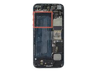
Remove the battery.
-
Adhere the battery, disconnect it, and continue reassembling your device.
-
-
-
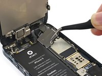
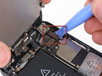
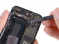
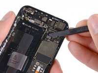
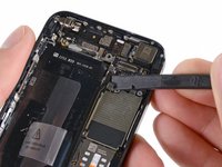
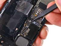
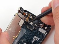
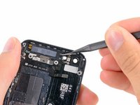
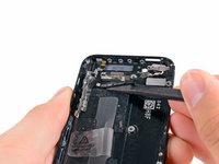
Use the tip of a spudger to pry the cellular data antenna cable connector up from its socket on the logic board, just above the speaker enclosure.
-
-
-
Remove the following two screws securing the top logic board bracket to the rear case:
-
One 1.5 mm Phillips screw
-
One 2.3 mm Phillips screw
-
-
-
Use the flat end of a spudger to disconnect the following three cables from the logic board:
-
Upper interconnect cable
-
Button assembly cable
-
Lower interconnect cable
-
-
-
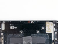
Remove the two 1.3 mm Phillips screws from the inner top of the rear case.
-
-
-
Remove the single 1.2 mm Phillips screw remaining in the mid-section logic board bracket.
-
-
-
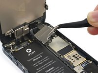
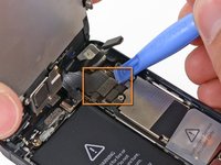
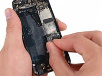
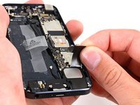
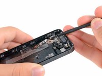
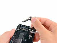
Use a spudger to pry the Lightning connector cable connector up from its socket on the logic board.
-
Gently peel the cable back and out of the way of the logic board.
-
-
-
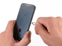
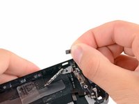
Depress the SIM card release on the right side of the iPhone with a SIM card eject tool or a bent paperclip to eject the SIM card tray.
-
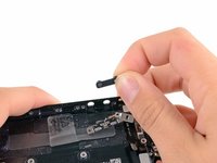
Remove the SIM card tray from the iPhone.
-
-
Инструмент, используемый на этом этапе:Standoff Screwdriver for iPhones$5.49
-
Remove the following screws securing the logic board to the rear case:
-
Two 2.3 mm Phillips screws
-
Two 2.7 mm standoff screws
-
One non-magnetic 2.7 mm standoff screw
-
-
Инструмент, используемый на этом этапе:Tweezers$4.99
-
Rotate the logic board assembly toward the battery side of the rear case.
-
The flash surround is adhered to the flash unit and the rear case. If it stays on the rear case remove with tweezers and mount it back on the flash unit.
-
Note: when reassembling your device, be sure that the lower interconnect cable is not tucked underneath the logic board.
-
-
-
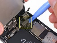
Use the tip of a spudger to pry the Wi-Fi antenna cable connector up from its socket on the underside of the logic board.
-
-
-
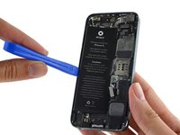
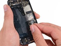
Remove the logic board assembly from the rear case.
-
While your logic board is out of your phone, keep it on a grounded anti-static mat to prevent any damage to the circuitry.
-
-
-
Remove the following screws securing the Lightning connector and speaker enclosure assembly to the rear case:
-
One 2.5 mm Phillips screw
-
Two 3.3 mm Phillips screws
-
One 2.9 mm Phillips screw
-
Two 1.5 mm Phillips screws
-
One 2.8 mm Phillips screw
-
-
-
Use the flat end of a spudger to gently pry the Lightning connector and speaker enclosure assembly cables up from the rear case.
-
-
-
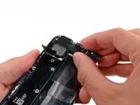
Remove the Lightning connector and speaker enclosure assembly from the rear case.
-
-
-
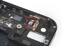
Remove the following screws securing the vibrator bracket and motor to the rear case:
-
One 2.3 mm Phillips screw
-
One 1.7 mm Phillips screw
-
One 1.6 mm Phillips screw in the top of the rear case
-
-
-
Remove eight 1.3 mm Phillips screws securing the front panel clips to the interior sides of the rear case.
-
-
-
Remove the following screws from the metal power switch bracket between the rear facing flash and camera windows:
-
Single 2.9 mm standoff screw
-
Single 1.6 mm Phillips screw
-
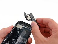
Remove the metal power switch bracket.
-
-
-
Remove the single 1.9 mm Phillips screw securing the power button bracket to the inside top of the rear case.
-
Use the tip of a spudger to rotate the power button cover down on its hinge.
-
-
-
Remove the power button from behind its cover in the rear case.
-
-
-
Use the tip of a spudger to press the power button cover in and lift it off of its hinge in the rear case.
-
-
-
Remove the following screws securing the volume and silence buttons to the side of the rear case:
-
One 1.3 mm Phillips screw
-
Two 1.8 mm Phillips screws
-
-
-
Pry the button cable away from the side of the rear case to expose the silence and volume buttons.
-
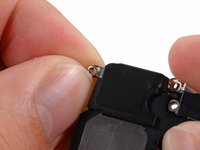
Remove the silence and volume buttons from the rear case.
-
-
-
Use the flat end of a spudger to pry the button cable up from the rear case.
-
Remove the button cable from the rear case.
-
-
-
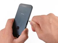
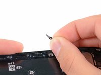
Remove the single 2.0 mm Phillips screw securing the SIM card eject lever to the rear case.
-
Remove the SIM card eject lever.
-


To reassemble your device, follow these instructions in reverse order.
Отменить: Я не выполнил это руководство.
200 человек успешно провели ремонт по этому руководству.


8 Комментарии к руководству
This guide does not describe removal of the wifi-antenna which seems to have taken place between step 32 and 34. For people new to electronics repair, such as myself, I feel this should be included in order to have a complete guide. I did a swap of the back casing yesterday myself, including the antenna and all went well (just a bit more nerve-wrecking removing parts not stated in the guide).
You're so right!
Replaced my rear case yesterday according to this guide, everything works :) just the power button pin was stuck on the old case and I had to make one from a paperclip, but still worked :)
can you fix an iPhone 5 into an iPhone 5 c Housing
All this is fine, but there is a padding to the mic, the lightning port, the audio jack and the speakers that is provided in the original casing but is not there in any of the replacement cases. Without it, there is a gap that is very much visible and susceptible to dust and water seepage. Is there any way to resolve this?