Перейти к основному содержанию

Эта версия возможно содержит некорректные исправления. Переключить на последнюю проверенную версию.

Абсолютно необходимое руководство
Это руководство предназначено только для использования в качестве обязательного условия для других руководств. Оно не полностью само по себе.

Выберете то, что вам нужно

  1. Этот шаг не переведен. Помогите перевести

    : шаг 1, изображение 1 из 1
    • Before disassembling your iPhone, discharge the battery below 25%. A charged lithium-ion battery can catch fire and/or explode if accidentally punctured.

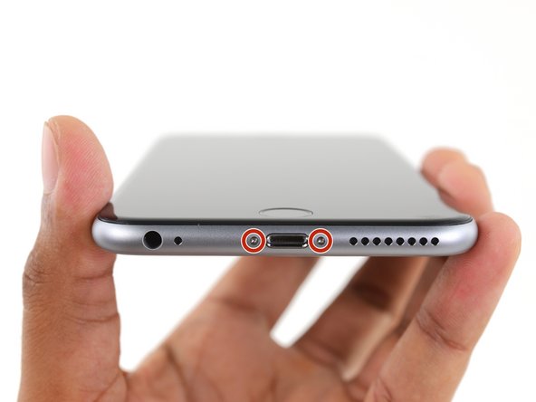
    • Power off your iPhone before beginning disassembly.

    • Remove the two 3.4 mm Pentalobe screws on either side of the Lightning port.

  2. Этот шаг не переведен. Помогите перевести

    : шаг 2, изображение 1 из 1
    Инструмент, используемый на этом этапе:
    Anti-Clamp
    $24.95
    Купить
    • If you don't have an Anti-Clamp, follow the next three steps to use a suction handle.

    • Apply mild heat to the lower edge of the iPhone using an iOpener or hair dryer for about a minute.

    • Heat softens the adhesive securing the display, making it easier to open.

  3. Этот шаг не переведен. Помогите перевести

    : шаг 3, изображение 1 из 1
    • Opening the display on the 6s Plus separates a thin strip of adhesive around the perimeter of the display. If you prefer to replace the adhesive, have a set of new adhesive strips ready before you continue. It's possible to complete the repair without replacing the adhesive, and you probably won't notice any difference in functionality.

    • Apply a suction cup to the lower left corner of the display assembly.

    • If your display is badly cracked, covering it with a layer of clear packing tape may allow the suction cup to adhere. Alternatively, very strong tape may be used instead of the suction cup. If all else fails, you can superglue the suction cup to the broken screen.

  4. Этот шаг не переведен. Помогите перевести

    : шаг 4, изображение 1 из 2 : шаг 4, изображение 2 из 2
    • Pull up on the suction cup with firm, constant pressure to create a slight gap between the front panel and rear case.

    • Pulling too hard may damage the display assembly. Apply just enough pressure to create a small gap between the display assembly and the rear case.

  5. Этот шаг не переведен. Помогите перевести

    : шаг 5, изображение 1 из 3 : шаг 5, изображение 2 из 3 : шаг 5, изображение 3 из 3
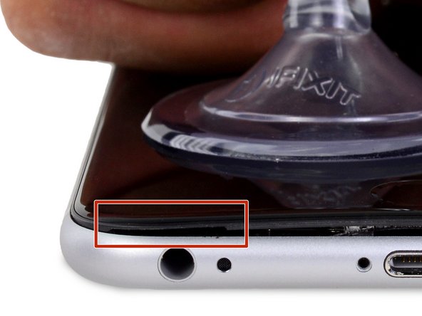
    • The safest place to pry from is the notch in the front panel above the headphone jack.

    • While still maintaining pressure on the suction cup, insert the flat tip of a spudger into the gap, directly above the headphone jack.

  6. Этот шаг не переведен. Помогите перевести

    : шаг 6, изображение 1 из 2 : шаг 6, изображение 2 из 2
    • Twist the spudger to widen the gap between the front panel and the rear case.

  7. Этот шаг не переведен. Помогите перевести

    : шаг 7, изображение 1 из 3 : шаг 7, изображение 2 из 3 : шаг 7, изображение 3 из 3
    • While firmly pulling up on the suction cup, slide the edge of the spudger under the bottom left corner of the display.

  8. Этот шаг не переведен. Помогите перевести

    : шаг 8, изображение 1 из 2 : шаг 8, изображение 2 из 2
    • Slide the tip of the spudger up the left side of the phone, between the front panel and the rear case.

  9. Этот шаг не переведен. Помогите перевести

    : шаг 9, изображение 1 из 2 : шаг 9, изображение 2 из 2
    • Insert the flat tip of the spudger under the right edge of the display.

    • Slide the spudger up the right side.

  10. Этот шаг не переведен. Помогите перевести

    : шаг 10, изображение 1 из 2 : шаг 10, изображение 2 из 2
    • Use a plastic opening tool to hold down the rear case while pulling up the suction cup to open the phone.

    • Do not remove the display completely, or you will damage the data cables connecting the display near the top edge of the iPhone.

  11. Этот шаг не переведен. Помогите перевести

    : шаг 11, изображение 1 из 2 : шаг 11, изображение 2 из 2
    • Pull up on the small nub on the suction cup to remove it from the display.

  12. Этот шаг не переведен. Помогите перевести

    : шаг 12, изображение 1 из 3 : шаг 12, изображение 2 из 3 : шаг 12, изображение 3 из 3
    • Gently grasp the display assembly and lift it up to open the phone, using the clips at the top of the front panel as a hinge.

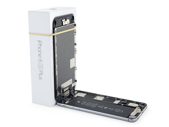
    • Open the display to about a 90º angle, and lean it against something to keep it propped up while you're working on the phone.

    • Don't open the display more than 90º—it is still connected to the top of the phone by the display, digitizer, and front camera cables which can tear easily.

    • Add a rubber band to keep the display securely in place while you work. This prevents undue strain on the display cables.

    • In a pinch, you can use an unopened canned beverage to support the display.

  13. Этот шаг не переведен. Помогите перевести

    : шаг 13, изображение 1 из 1
    Инструмент, используемый на этом этапе:
    Magnetic Project Mat
    $19.95
    Купить
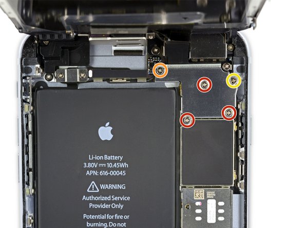
    • Remove two Phillips screws securing the battery connector bracket to the logic board, of the following lengths:

    • One 2.9 mm screw

    • One 2.3 mm screw

    • Throughout this guide, keep careful track of your screws so that each one goes back where it came from during reassembly. Installing a screw in the wrong place can cause permanent damage.

  14. Этот шаг не переведен. Помогите перевести

    : шаг 14, изображение 1 из 2 : шаг 14, изображение 2 из 2
    • Remove the battery connector bracket.

  15. Этот шаг не переведен. Помогите перевести

    : шаг 15, изображение 1 из 3 : шаг 15, изображение 2 из 3 : шаг 15, изображение 3 из 3
    • Use a spudger or a clean fingernail to disconnect the battery connector by prying it straight up off the logic board.

  16. Этот шаг не переведен. Помогите перевести

    : шаг 16, изображение 1 из 3 : шаг 16, изображение 2 из 3 : шаг 16, изображение 3 из 3
    • Bend the connector back to ensure it doesn't make contact and power the iPhone on while you're working on it.

  17. Этот шаг не переведен. Помогите перевести

    : шаг 17, изображение 1 из 1
    • Remove the following Phillips screws:

    • Three 1.3 mm screws

    • One 1.6 mm screw

    • One 3.0 mm screw

    • During reassembly, it's critical to place this 3.0 mm screw in the top-right corner of the bracket. Placing it anywhere else may damage the logic board.

  18. Этот шаг не переведен. Помогите перевести

    : шаг 18, изображение 1 из 2 : шаг 18, изображение 2 из 2
    • Remove the display cable bracket.

  19. Этот шаг не переведен. Помогите перевести

    : шаг 19, изображение 1 из 2 : шаг 19, изображение 2 из 2
    • Be careful to only pry up on the connector itself and not the socket on the logic board.

    • Use a plastic opening tool to disconnect the front-facing camera and sensor cable connector.

  20. Этот шаг не переведен. Помогите перевести

    : шаг 20, изображение 1 из 2 : шаг 20, изображение 2 из 2
    • Use a plastic opening tool to disconnect the digitizer cable by prying it straight up from its socket on the logic board.

    • When reconnecting the digitizer cable, do not press the center of the connector. Press one end of the connector, then press the opposite end. Pressing in the center of the connector can bend the component and cause digitizer damage.

  21. Этот шаг не переведен. Помогите перевести

    : шаг 21, изображение 1 из 2 : шаг 21, изображение 2 из 2
    • Make sure the battery is disconnected before you disconnect or reconnect the cable in this step.

    • Disconnect the home button/fingerprint sensor cable by prying it straight up from its socket on the logic board.

  22. Этот шаг не переведен. Помогите перевести

    : шаг 22, изображение 1 из 2 : шаг 22, изображение 2 из 2
  23. Этот шаг не переведен. Помогите перевести

    : шаг 23, изображение 1 из 3 : шаг 23, изображение 2 из 3 : шаг 23, изображение 3 из 3
    • Peel up any tape covering the iSight camera bracket screws.

  24. Этот шаг не переведен. Помогите перевести

    : шаг 24, изображение 1 из 1
    • Remove the following Phillips screws over the camera bracket:

    • One 1.9 mm screw

    • One 2.4 mm screw

  25. Этот шаг не переведен. Помогите перевести

    : шаг 25, изображение 1 из 2 : шаг 25, изображение 2 из 2
    • Remove the iSight camera bracket.

  26. Этот шаг не переведен. Помогите перевести

    : шаг 26, изображение 1 из 2 : шаг 26, изображение 2 из 2
    • Disconnect the iSight camera connector from its socket on the logic board.

    • Be sure to pry up only the connector and not the socket on the logic board.

  27. Этот шаг не переведен. Помогите перевести

    : шаг 27, изображение 1 из 2 : шаг 27, изображение 2 из 2
    • Insert the flat end of the spudger between the iSight camera and rear casing.

    • Gently pry the camera out from its housing.

  28. Этот шаг не переведен. Помогите перевести

    : шаг 28, изображение 1 из 2 : шаг 28, изображение 2 из 2
    • Remove the iSight camera.

  29. Этот шаг не переведен. Помогите перевести

    : шаг 29, изображение 1 из 2 : шаг 29, изображение 2 из 2
    • Insert a SIM eject tool into the hole in the SIM tray.

    • Press to eject the SIM tray.

  30. Этот шаг не переведен. Помогите перевести

    : шаг 30, изображение 1 из 1
    • Remove the SIM tray.

    • When reinserting the SIM tray, be sure to orient the tray such that the SIM eject hole is on the bottom.

  31. Этот шаг не переведен. Помогите перевести

    : шаг 31, изображение 1 из 1
    • Remove the single 1.4 mm Phillips screw holding the NFC bracket in place.

  32. Этот шаг не переведен. Помогите перевести

    : шаг 32, изображение 1 из 2 : шаг 32, изображение 2 из 2
    • Remove the NFC bracket.

  33. Этот шаг не переведен. Помогите перевести

    : шаг 33, изображение 1 из 1
    • Remove the two 2.7 mm Phillips screws securing the audio control cable bracket to the logic board.

  34. Этот шаг не переведен. Помогите перевести

    : шаг 34, изображение 1 из 2 : шаг 34, изображение 2 из 2
    • Remove the audio control cable bracket.

  35. Этот шаг не переведен. Помогите перевести

    : шаг 35, изображение 1 из 2 : шаг 35, изображение 2 из 2
    • Disconnect the audio control cable by prying its connector straight up from its socket on the logic board.

  36. Этот шаг не переведен. Помогите перевести

    : шаг 36, изображение 1 из 2 : шаг 36, изображение 2 из 2
    • Disconnect the cellular antenna cable by prying its connector straight up from its respective socket on the logic board.

  37. Этот шаг не переведен. Помогите перевести

    : шаг 37, изображение 1 из 2 : шаг 37, изображение 2 из 2
    • Disconnect the Wi-Fi diversity antenna cable by prying its connector up from the logic board.

  38. Этот шаг не переведен. Помогите перевести

    : шаг 38, изображение 1 из 2 : шаг 38, изображение 2 из 2
    • Disconnect the power button flex cable from its socket on the logic board.

  39. Этот шаг не переведен. Помогите перевести

    : шаг 39, изображение 1 из 2 : шаг 39, изображение 2 из 2
    • Disconnect the antenna cable by prying it up from the logic board.

  40. Этот шаг не переведен. Помогите перевести

    : шаг 40, изображение 1 из 2 : шаг 40, изображение 2 из 2
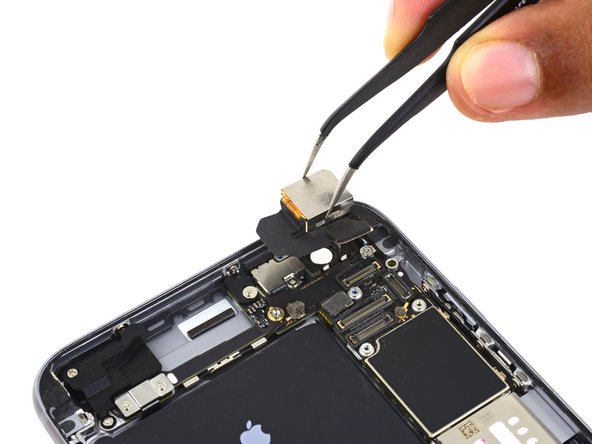
    • Use the flat end of a spudger to disconnect the Lightning connector flex cable from the logic board.

  41. Этот шаг не переведен. Помогите перевести

    : шаг 41, изображение 1 из 3 : шаг 41, изображение 2 из 3 : шаг 41, изображение 3 из 3
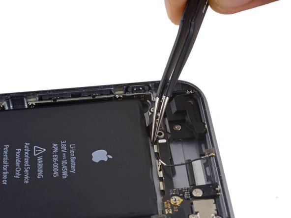
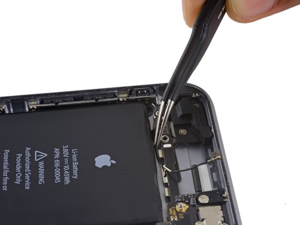
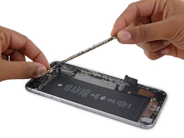
    • Deroute the antenna cable from the two clips on the right edge of the logic board.

  42. Этот шаг не переведен. Помогите перевести

    : шаг 42, изображение 1 из 2 : шаг 42, изображение 2 из 2
    Инструмент, используемый на этом этапе:
    Standoff Screwdriver for iPhones
    $5.49
    Купить
    • Remove the following screws:

    • One 1.3 mm Phillips screw

    • One 2.6 mm Phillips screw

    • One 2.2 mm standoff screw

    • Standoff screws are best removed using a standoff screwdriver or bit.

    • In a pinch, a small flathead screwdriver will do the job—but use extra caution to ensure it doesn't slip and damage surrounding components.

  43. Этот шаг не переведен. Помогите перевести

    : шаг 43, изображение 1 из 2 : шаг 43, изображение 2 из 2
    • Remove the bracket.

  44. Этот шаг не переведен. Помогите перевести

    : шаг 44, изображение 1 из 2 : шаг 44, изображение 2 из 2
    • Deroute the upper left cellular antenna cable from the first logic board clip by nudging it out from under the clip, towards the battery.

  45. Этот шаг не переведен. Помогите перевести

    : шаг 45, изображение 1 из 3 : шаг 45, изображение 2 из 3 : шаг 45, изображение 3 из 3
    • Continue derouting the cellular antenna cable from the second and third logic board clips.

    • Use the pointed tip of a spudger to gently pry the cellular antenna cable from the middle logic board clip.

    • Don't try to remove it by pulling on the cable, as it will tear easily.

    • In order for the cable to reach its socket on the logic board, you must route it above the logic board and underneath the audio control flex cable, as shown in the first photo.

  46. Этот шаг не переведен. Помогите перевести

    : шаг 46, изображение 1 из 1
    • Remove the final 2.0 mm Phillips screw directly below the SIM card reader.

  47. Этот шаг не переведен. Помогите перевести

    : шаг 47, изображение 1 из 3 : шаг 47, изображение 2 из 3 : шаг 47, изображение 3 из 3
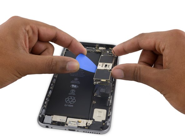
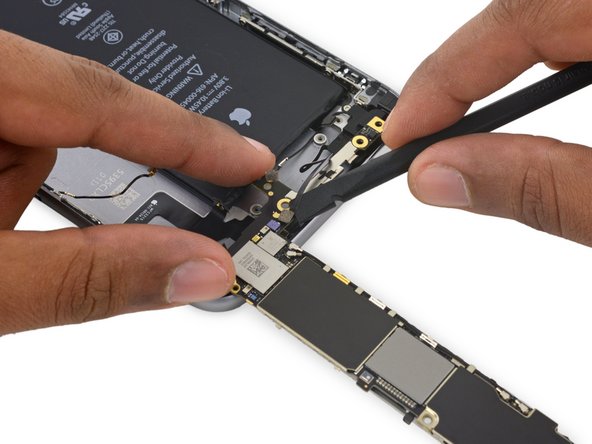
    • Carefully raise—but do not remove—the logic board, lifting it from the bottom edge nearest the Lightning connector.

  48. Этот шаг не переведен. Помогите перевести

    : шаг 48, изображение 1 из 3 : шаг 48, изображение 2 из 3 : шаг 48, изображение 3 из 3
    • Tip the logic board up to a vertical position to expose the single antenna connector on the underside, near the top edge of the board.

    • Do not attempt to fully remove the logic board yet, as the Wi-Fi/Bluetooth antenna is still connected to the underside of the board.

  49. Этот шаг не переведен. Помогите перевести

    : шаг 49, изображение 1 из 2 : шаг 49, изображение 2 из 2
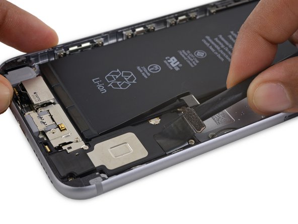
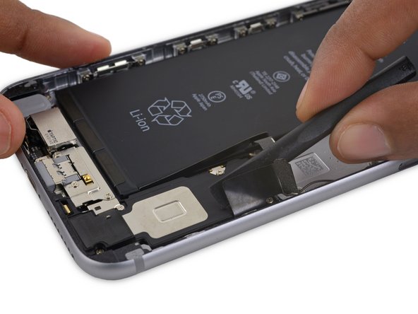
    • Gently lay the logic board upside-down, with the top portion resting against the rear case of the iPhone.

    • Use the flat end of the spudger to disconnect the Wi-Fi/Bluetooth antenna cable from its socket on the back of the logic board.

  50. Этот шаг не переведен. Помогите перевести

    : шаг 50, изображение 1 из 1
    • Remove the logic board.

  51. Этот шаг не переведен. Помогите перевести

    : шаг 51, изображение 1 из 3 : шаг 51, изображение 2 из 3 : шаг 51, изображение 3 из 3
    • Use the flat end of a spudger to peel the Lightning connector flex cable off the speaker.

  52. Этот шаг не переведен. Помогите перевести

    : шаг 52, изображение 1 из 2 : шаг 52, изображение 2 из 2
    • Remove the following three Phillips screws from the Taptic Engine cable bracket:

    • Two 3.5 mm screws

    • One 2.7 mm screw

    • Remove the bracket.

  53. Этот шаг не переведен. Помогите перевести

    : шаг 53, изображение 1 из 1
    • Remove the five Phillips screws securing the speaker to the rear case:

    • Two 2.7 mm screws

    • One 2.5 mm screw

    • One 1.5 mm screw

    • One 1.7 mm screw

  54. Этот шаг не переведен. Помогите перевести

    : шаг 54, изображение 1 из 3 : шаг 54, изображение 2 из 3 : шаг 54, изображение 3 из 3
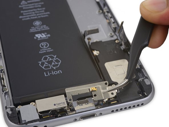
    • Deroute the Wi-Fi diversity antenna cable from its rubber sleeve.

    • If the white water damage indicator sticker makes it difficult to deroute the antenna cable, gently peel the sticker back for better access.

  55. Этот шаг не переведен. Помогите перевести

    : шаг 55, изображение 1 из 2 : шаг 55, изображение 2 из 2
    Инструмент, используемый на этом этапе:
    Tweezers
    $4.99
    Купить
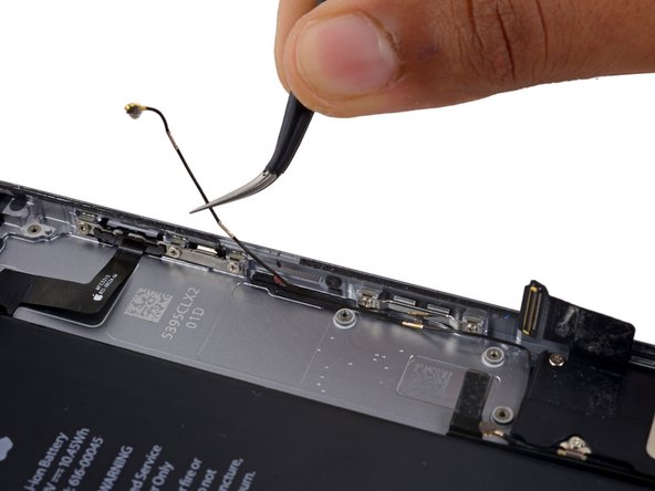
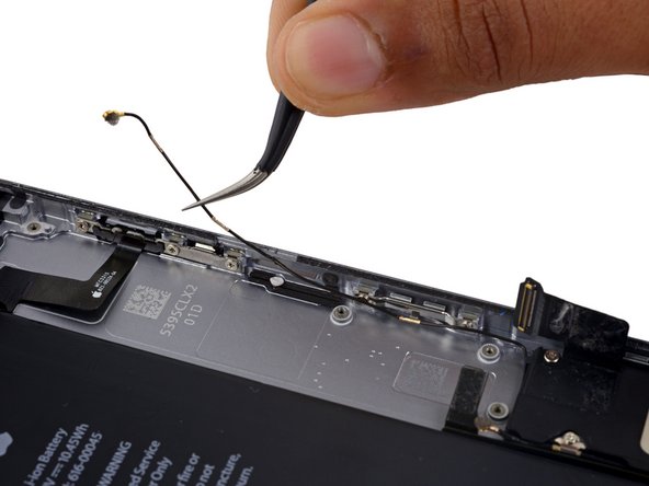
    • Use a pair of tweezers to disconnect the Wi-Fi diversity antenna cable from the Lightning connector flex cable.

  56. Этот шаг не переведен. Помогите перевести

    : шаг 56, изображение 1 из 1
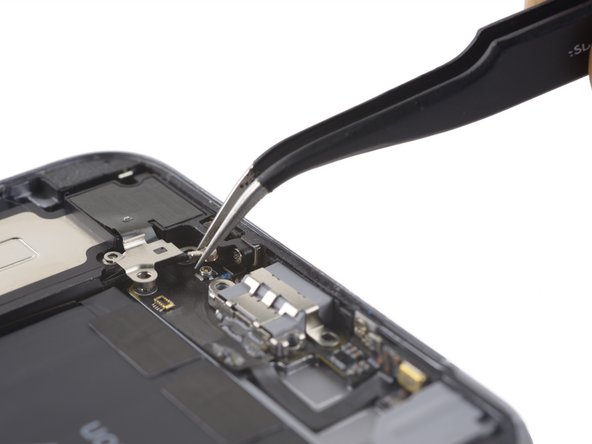
    • Remove the final 2.6 mm Phillips screw securing the speaker to the rear case.

  57. Этот шаг не переведен. Помогите перевести

    : шаг 57, изображение 1 из 3 : шаг 57, изображение 2 из 3 : шаг 57, изображение 3 из 3
    • Use the flat end of a spudger to lift the speaker assembly out of its housing.

    • Remove the speaker assembly.

Финишная черта

Evan Noronha

Участник с: 02/05/15

223 674 Репутация

Автор 168 руководств

0 Комментариев

Добавить комментарий

Просмотр статистики:

За последние 24часов: 0

За последние 7 дней: 0

За последние 30 дней: 12

За всё время: 393