Перейти к основному содержанию
Присоединяйся к сообществу ремонтников - Создай аккаунт

BUSY Bar Disassembly

Выберете то, что вам нужно

    1. BUSY Bar Disassembly, Remove the back cover: шаг 1, изображение 1 из 3 BUSY Bar Disassembly, Remove the back cover: шаг 1, изображение 2 из 3 BUSY Bar Disassembly, Remove the back cover: шаг 1, изображение 3 из 3
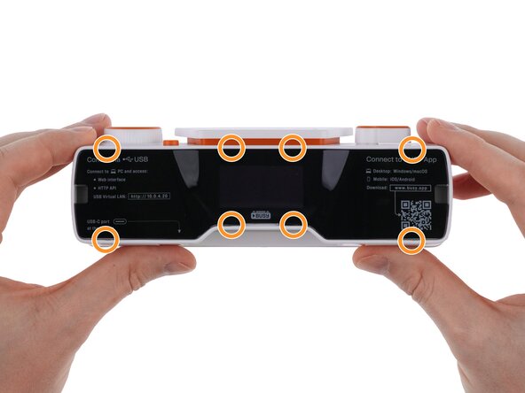
      • The back cover is held in place by 8 clips.

      • Use a plastic card to release one of the clips near the center at the bottom of the back cover.

      • Gently release the remaining clips until the back cover comes off completely.

      Спросите у FixBot

      Добавить комментарий

    2. BUSY Bar Disassembly, Remove the screws: шаг 2, изображение 1 из 3 BUSY Bar Disassembly, Remove the screws: шаг 2, изображение 2 из 3 BUSY Bar Disassembly, Remove the screws: шаг 2, изображение 3 из 3
      • Use a PH1 Phillips screwdriver to remove 1 screw from the bottom and 4 screws from the back of the device.

      Спросите у FixBot

      Добавить комментарий

    3. BUSY Bar Disassembly, Pull out the front display unit: шаг 3, изображение 1 из 3 BUSY Bar Disassembly, Pull out the front display unit: шаг 3, изображение 2 из 3 BUSY Bar Disassembly, Pull out the front display unit: шаг 3, изображение 3 из 3
      • Do not pull the display unit too far out of the housing, as this may damage the display cable or connectors.

      • Do not disconnect the display cable. The battery must be disconnected first.

      • Use a plastic card to release the 2 latches on top of the front display.

      • Gently pull the front display unit out toward the right.

      Спросите у FixBot

      Добавить комментарий

    4. BUSY Bar Disassembly, Remove the battery: шаг 4, изображение 1 из 3 BUSY Bar Disassembly, Remove the battery: шаг 4, изображение 2 из 3 BUSY Bar Disassembly, Remove the battery: шаг 4, изображение 3 из 3
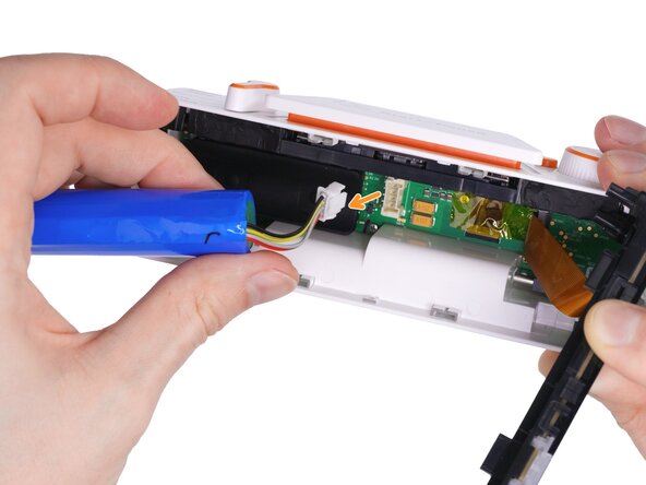
      • Gently move the battery to the left so you can access the connector.

      • Use tweezers or your fingertip to press the connector latch.

      • Pull the battery connector to disconnect it from the PCB.

      Спросите у FixBot

      Добавить комментарий

    5. BUSY Bar Disassembly, Remove the front display unit: шаг 5, изображение 1 из 3 BUSY Bar Disassembly, Remove the front display unit: шаг 5, изображение 2 из 3 BUSY Bar Disassembly, Remove the front display unit: шаг 5, изображение 3 из 3
      • Use a spudger to release the display cable connector latch.

      • Pull the cable in the direction indicated by the arrow.

      • Remove the front display unit.

      Спросите у FixBot

      Добавить комментарий

    6. BUSY Bar Disassembly, Remove the battery pad: шаг 6, изображение 1 из 2 BUSY Bar Disassembly, Remove the battery pad: шаг 6, изображение 2 из 2
      • Use your fingers to lift and remove the silicone battery pad.

      Спросите у FixBot

      Добавить комментарий

    7. BUSY Bar Disassembly, Disconnect the cable connecting the main and control PCBs: шаг 7, изображение 1 из 3 BUSY Bar Disassembly, Disconnect the cable connecting the main and control PCBs: шаг 7, изображение 2 из 3 BUSY Bar Disassembly, Disconnect the cable connecting the main and control PCBs: шаг 7, изображение 3 из 3
      • Use tweezers to remove the yellow tape from the connector on the main PCB.

      • Use a halberd spudger to release the connector latch.

      • Use tweezers to disconnect the cable from the connector.

      Спросите у FixBot

      Добавить комментарий

    8. BUSY Bar Disassembly, Disconnect the back display: шаг 8, изображение 1 из 2 BUSY Bar Disassembly, Disconnect the back display: шаг 8, изображение 2 из 2
      • Use a halberd spudger to release the latch on the display connector.

      • Gently press the flex cable with your finger and slide it out of the connector.

      Спросите у FixBot

      Добавить комментарий

    9. BUSY Bar Disassembly, Remove the speaker: шаг 9, изображение 1 из 3 BUSY Bar Disassembly, Remove the speaker: шаг 9, изображение 2 из 3 BUSY Bar Disassembly, Remove the speaker: шаг 9, изображение 3 из 3
      • Use a spudger to pry up the speaker connector and disconnect it.

      • Use tweezers to remove the speaker from the device housing.

      Спросите у FixBot

      Добавить комментарий

    10. BUSY Bar Disassembly, Remove the control knobs: шаг 10, изображение 1 из 3 BUSY Bar Disassembly, Remove the control knobs: шаг 10, изображение 2 из 3 BUSY Bar Disassembly, Remove the control knobs: шаг 10, изображение 3 из 3
      • Use a spudger or an opening tool to remove the scroll wheel, holding it with your other hand to prevent bending.

      • Using both hands, lift up the Start/Pause button knob to remove it.

      • Use a spudger or an opening tool to remove the mode selector cover.

      Спросите у FixBot

      Добавить комментарий

    11. BUSY Bar Disassembly, Remove the main PCB: шаг 11, изображение 1 из 3 BUSY Bar Disassembly, Remove the main PCB: шаг 11, изображение 2 из 3 BUSY Bar Disassembly, Remove the main PCB: шаг 11, изображение 3 из 3
      • Use a PH1 screwdriver to remove the 3 screws securing the PCB.

      • Carefully lift the PCB out of the device housing.

      Спросите у FixBot

      Добавить комментарий

    12. BUSY Bar Disassembly, Remove the control unit: шаг 12, изображение 1 из 3 BUSY Bar Disassembly, Remove the control unit: шаг 12, изображение 2 из 3 BUSY Bar Disassembly, Remove the control unit: шаг 12, изображение 3 из 3
      • Peel off the 2 black stickers from the control unit.

      • Use a spudger to release the 2 clips on the sides of the unit.

      • Use a halberd spudger to release the 2 clips closer to the center.

      • Remove the control unit from the device housing.

      Спросите у FixBot

      Добавить комментарий

    13. BUSY Bar Disassembly, Remove the Back button cap and the light guides: шаг 13, изображение 1 из 3 BUSY Bar Disassembly, Remove the Back button cap and the light guides: шаг 13, изображение 2 из 3 BUSY Bar Disassembly, Remove the Back button cap and the light guides: шаг 13, изображение 3 из 3
      • Remove the 2 white status indicator light guides by lifting them from the edge with your finger.

      • Use a spudger to release the latch securing the Back button cover.

      • Remove the Back button cover.

      Спросите у FixBot

      Добавить комментарий

    14. BUSY Bar Disassembly, Remove the button stabilizer: шаг 14, изображение 1 из 3 BUSY Bar Disassembly, Remove the button stabilizer: шаг 14, изображение 2 из 3 BUSY Bar Disassembly, Remove the button stabilizer: шаг 14, изображение 3 из 3
      • Remove the 3 screws from the bottom of the control unit.

      • Remove the stabilizer holder.

      Спросите у FixBot

      Добавить комментарий

    15. BUSY Bar Disassembly, Remove the control PCB from the housing: шаг 15, изображение 1 из 3 BUSY Bar Disassembly, Remove the control PCB from the housing: шаг 15, изображение 2 из 3 BUSY Bar Disassembly, Remove the control PCB from the housing: шаг 15, изображение 3 из 3
      • The control PCB is secured in the plastic housing by 5 latches.

      • Gently pull the PCB away from the plastic housing. You can pull by the scroll wheel or the mode selector.

      • Release the latches by bending them outward from the PCB using your finger, a spudger, or an opening tool.

      • Once all latches are released, remove the PCB from the housing.

      Спросите у FixBot

      Добавить комментарий

    16. BUSY Bar Disassembly, Disconnect the cable from the control PCB: шаг 16, изображение 1 из 2 BUSY Bar Disassembly, Disconnect the cable from the control PCB: шаг 16, изображение 2 из 2
      • Use a spudger to carefully release the connector latch.

      • Remove the flex cable.

      Спросите у FixBot

      Добавить комментарий

    17. BUSY Bar Disassembly, Remove the front display back cover: шаг 17, изображение 1 из 3 BUSY Bar Disassembly, Remove the front display back cover: шаг 17, изображение 2 из 3 BUSY Bar Disassembly, Remove the front display back cover: шаг 17, изображение 3 из 3
      • The back cover of the front display unit is secured by 6 latches.

      • Use a spudger or a plastic card to carefully release the latches around the front display.

      • Remove the back cover of the front display unit.

      Спросите у FixBot

      Добавить комментарий

    18. BUSY Bar Disassembly, Disassemble the front display unit: шаг 18, изображение 1 из 3 BUSY Bar Disassembly, Disassemble the front display unit: шаг 18, изображение 2 из 3 BUSY Bar Disassembly, Disassemble the front display unit: шаг 18, изображение 3 из 3
      • The front display unit consists of a display PCB with LEDs and LED drivers, a plastic light separator, a matte light-diffusing film, and an outer tinted glass.

      • Remove the display PCB from the front display unit.

      • Remove the light separator.

      • Remove the light-diffusing film.

      Спросите у FixBot

      Добавить комментарий

    19. BUSY Bar Disassembly, Remove the light guide and the cable from the display PCB: шаг 19, изображение 1 из 3 BUSY Bar Disassembly, Remove the light guide and the cable from the display PCB: шаг 19, изображение 2 из 3 BUSY Bar Disassembly, Remove the light guide and the cable from the display PCB: шаг 19, изображение 3 из 3
      • Tilt the ambient light sensor light guide forward to disconnect it from the display PCB.

      • Use a spudger to release the flex cable connector latch.

      • Pull the flex cable in the direction indicated by the arrow to remove it.

      Спросите у FixBot

      Добавить комментарий

    20. BUSY Bar Disassembly, Remove the monitor mount: шаг 20, изображение 1 из 3 BUSY Bar Disassembly, Remove the monitor mount: шаг 20, изображение 2 из 3 BUSY Bar Disassembly, Remove the monitor mount: шаг 20, изображение 3 из 3
      • The 2 black polyurethane friction elements on the mount’s pivot create rotational resistance to hold the leg in intermediate positions.

      • Use a spudger to slide the 2 friction elements toward the center of the device. They move together with the short metal shafts and can then be removed from the housing.

      • Press the mount leg downward toward the center of the device (following the orange arrow).

      • At the same time push the mount leg sideways (following the red arrow) to release it from the slot.

      • Repeat these steps for the opposite side of the leg to remove it.

      Спросите у FixBot

      Добавить комментарий

    21. BUSY Bar Disassembly, Device fully disassembled: шаг 21, изображение 1 из 1
      • The device is now fully disassembled. The picture shows all its components.

      Спросите у FixBot

      Добавить комментарий

Заключение

To reassemble the device, follow these steps in reverse order.

Отменить: Я не выполнил это руководство.

3 человек успешно провели ремонт по этому руководству.

Flipper Devices

Участник с: 06/29/22

1 108 Репутация

Автор 3 руководств

0 Комментарии к руководству

Добавить комментарий

Статистика просмотров:

За последние 24 часов: 4

За последние 7 дней: 35

За последние 30 дней: 191

За всё время: 763