Введение
This guide will demonstrate how to replace the electrical assembly in a Dremel 4000.
Выберете то, что вам нужно
-
-
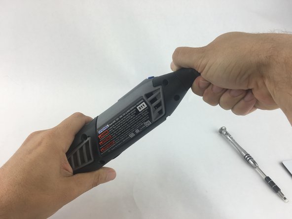
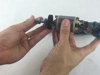
Start by removing the housing cap by unscrewing it.
-
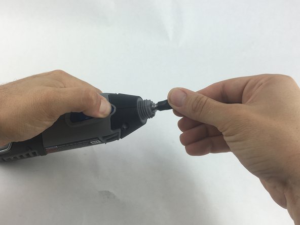
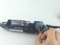
Next, unscrew the now exposed collet nut while holding down the shaft lock button.
 Спросите у FixBot
-
-
-
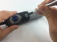
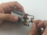
Remove the brush caps (one on each side) by using a flathead screwdriver bit.
-
-
-
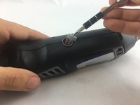
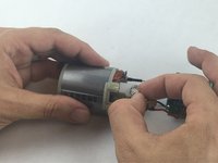
Using the Torx 15 screwdriver tip, remove the 5 screws (12.5 mm) that hold the casing together.
-
-
-
Use a plastic opening tool to gently wedge apart the hard plastic threads.
-
-
-
-
Use your hands to carefully remove the back casing so that none of the components fall out.
-
-
-
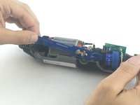
To clear access to the electrical assembly, remove the variable speed dial cap and blue power lever, and set them aside.
-
-
-
Using your fingers, carefully pull the circuit board from the casing. This will make it easier to remove the power cord.
-
-
-
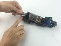
Each wire is fed through a small opening on the circuit board and held with a flat head screw.
-
Loosen the screw just enough to remove the wire by gently pulling it with your hand.
-
-
-
Carefully remove both wires from circuit board with your hands.
-
-
-
Carefully pull up on the shaft to lift out of the casing.
-
-
-
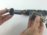
Firmly hold the field assembly in one hand and the bearing assembly in the other.
-
Carefully slide the bearing assemble out of the field assembly.
-
-
-
Firmly hold the field assembly in one hand, and carefully pull free the red and black wires that connects the electrical assembly to the field assembly.
-


To reassemble your device, follow these instructions in reverse order.
Отменить: Я не выполнил это руководство.
29 человек успешно провели ремонт по этому руководству.
Команда

USF Tampa, Team 15-4, Remmell Spring 2016 Участник USF Tampa, Team 15-4, Remmell Spring 2016
USFT-REMMELL-S16S15G4
4 членов
Автор 17 руководств
15 Комментарии к руководству
One of the brush holders has a component...small capacitor... ten cent part. If somebody can identify the value of the component, I could fix mine now that I've replaced the control board and still won't start. I shorted across the component and suddenly came to life.
DF110S 110c Thermal Fuse 16A 250V
“Thermal fuse DF is an one shot device, after operating function have to be replaced.”
Anyone with info about the third wire (on mine is blue ending with a small copper clip) serves? This is connected off of the switch, labeled W5 on the circuit board. [Edit. It is a ground] I suspect it is a feed back wire for speed sensor? But where does it attach? Some wear on the abovementioned capacitor crossing one of the brushes. Anny ideas?
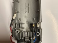
You see the copper bushing slot at the top of the picture (next to the guy’s index finger) from step 9? Directly underneath it where the slot sits, there’s a tiny notch in the gray frame. Once you pull off the bushing slot from the frame (if you haven’t already), slide the small copper clip (from your 3rd blue wire) onto that notch. Then you push the bushing slot back onto the frame where it was. Essentially, the copper clip is “grounded” to that bushing slot.
An even better photo in step 11 showing the copper clip on the blue wire located beneath the copper brush holder