Введение
This repair guide was authored by the iFixit staff and hasn’t been endorsed by Google. Learn more about our repair guides here.
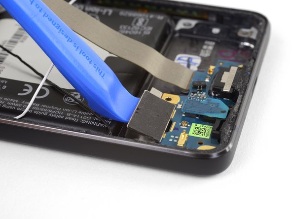
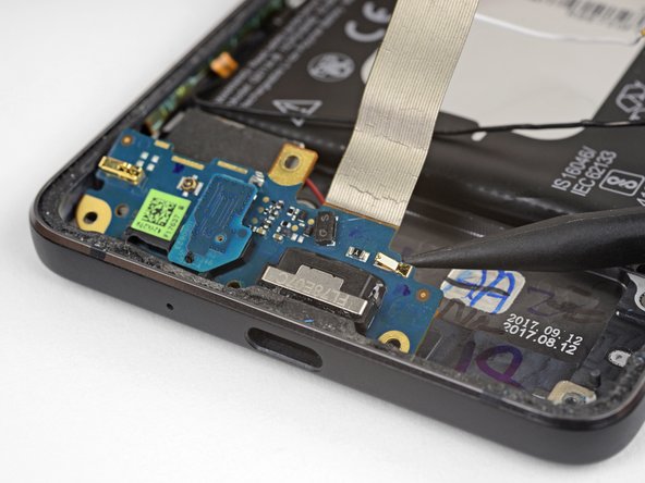
Use this guide to replace the charging assembly. The charging assembly contains the USB-C port and is connected to the vibration motor.
Выберете то, что вам нужно
-
-
If your display glass is cracked, keep further breakage contained and prevent bodily harm during your repair by taping the glass. This also makes a smooth surface allowing the suction cup to bond.
-
Apply a suction cup as close to the volume button edge of the phone as you can while avoiding the curved edge.
-
-
-
Pull up on the suction cup with firm, constant pressure and insert an opening pick between the front panel and rear case.
-
-
-
Do not insert the pick more than 9 mm into the bottom edge of the phone. If the pick contacts the folded portion of the OLED panel it can damage the display.
-
Only make very shallow cuts in the upper left corner, prying deeply can damage the front-facing camera.
-
-
-
Slide the opening pick up the right side of the phone to separate the display adhesive.
-
-
-
Slide the opening pick around the upper-right corner and along the top edge of the phone.
-
-
-
Slide the pick around the upper-left corner of the phone and down the left edge of the phone.
-
-
-
Slide the pick around the bottom-left corner and along the bottom of the phone. Keep pick at a slight angle away from the screen to avoid damage to the OLED corners.
-
-
-
Carefully lay the display down on top of the rear case as shown, making sure not to crease or tear the display ribbon cable.
-
Remove the two 4.0 mm T5 Torx screws securing the display cable bracket.
-
-
-
-
Use the point of a spudger to lift the display cable connector up and out of its socket on the motherboard.
-
-
-
Apply a heated iOpener to the proximity sensor on the top edge of the midframe for two minutes to soften its adhesive.
-
-
-
Slide the point of a spudger under the proximity sensor cable, starting from the side closest to the front-facing camera.
-
Gently lift the edge of the sensor cable until the sensor is perpendicular to the midframe.
-
-
-
Peel back the small piece of tape covering the screw below the earpiece speaker. Peel back any tape covering other screws as well.
-
Remove the following screws securing the midframe:
-
Eleven 3.7 mm Phillips screws
-
One 4 mm T5 Torx screw
-
-
-
Insert an opening tool into the notch in the midframe near the hold button.
-
Pry the midframe up enough to create a gap between it and the phone case. The midframe cannot yet be completely removed.
-
-
-
Lift the midframe up starting from the bottom edge.
-
When the midframe starts to make about a 45° with the rest of the phone, lift the midframe straight up and away from the phone.
-
As you lift the midfame, carefully guide the proximity sensor through the small slot in the midframe.
-
-
-
Use the flat end of a spudger to disconnect the battery connector.
-
-
-
Use the flat end of a spudger to disconnect the charging assembly connector.
-
-
-
Use the point of a spudger to pry the white antenna cable connector straight up and disconnect it from the charging assembly board.
-
-
-
Use tweezers to pull the white antenna cable straight up and out of the metal clips on the board and out of the channel on the loudspeaker.
-
Move the cable to the left of the phone to keep it out of the way of the loudspeaker.
-
-
-
Use the tip of a spudger pry the black antenna cable connector straight up and disconnect it.
-
-
-
Use tweezers to lift the black antenna cable out of its channel on the loudspeaker.
-
Move the cable toward the top of the phone to keep it out of the way of the loudspeaker.
-
-
-
Use the tip of a spudger to gently push the speaker cable connector out of its socket horizontally, alternating pushing either side of the connector out a little bit at a time.
-
-
-
Use an opening tool to pry the loudspeaker assembly up slightly from its recess in the phone.
-
Hold the silver charging assembly cable out of the way while you're working, but be careful not to bend it too far or apply too much strain where it connects to the charging assembly.
-
-
-
Rotate the top right corner of the loudspeaker toward the top of the phone while sliding the whole assembly to the right.
-
Remove the loudspeaker.
-
-
-
Use an opening tool the gently lift the vibration motor and separate it from the adhesive holding it to the phone.
-
-
-
Use the point of a spudger to lift the top of the charging assembly away from the phone.
-
-
-
Make sure the vibration motor is not adhered to the phone, then gently lift the charging assembly out of the the phone, lifting the motor out at the same time.
-
Remove the microphone board and transfer it to the new charging assembly.
-
Compare your new replacement part to the original part—you may need to transfer remaining components or remove adhesive backings from the new part before installing.
To reassemble your device, follow the above steps in reverse order.
Take your e-waste to an R2 or e-Stewards certified recycler.
Repair didn’t go as planned? Check out our Answers community for troubleshooting help.
Отменить: Я не выполнил это руководство.
14 участников успешно повторили данное руководство.
3 Комментариев
I’m fairly disappointed with this. It didn’t say that the microphone chip had to be transferred to a new part. This caused me to take this phone apart twice.
Is the charging assembly PCBA really responsible for battery charging?
Or is it just supplying the 5V from the charger thru the flex to the motherboard, which is in fact responsible for the charging?
There are additional "data" pins on the battery, which I suppose are also used during charging to report battery temperature etc., but these pins are not directly connected to the flex connector.
So I think that the motherboard is responsible for charging.
My phone is not charging, but i can measure the 5V from the USB on the motherboard connector at the end of the flex. Will it help to change the charging assembly?


