Введение
This is a prerequisite only guide. It disconnects most of the connectors and removes most of the screws to take the motherboard out. The shots are taken such that you can’t see whether the Taptic Engine is out or not.
Note that each iPhone's logic board and Touch ID fingerprint sensor are paired at the factory, so replacing the logic board will disable Touch ID unless you also install a replacement home button that has been properly paired to your new logic board.
Opening the iPhone 8 will damage the waterproof seals on the display. If you do not replace the adhesive seals, your phone will function normally, but will no longer be water-resistant.
Выберете то, что вам нужно
-
-
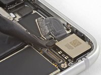
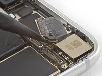
Use the flat end of a spudger to disconnect the camera cable connector by prying it straight up from its socket.
-
-
Инструмент, используемый на этом этапе:Standoff Screwdriver for iPhones$5.49
-
Remove the two screws securing the rear-facing camera bracket:
-
One 3.0 mm standoff screw
-
One 3.1 mm Phillips screw
-
-
-
Use the point of a spudger to disconnect the flash connector from its socket by prying it straight up.
-
-
-
Remove the two screws securing the upper cable bracket:
-
One 2.9 mm Phillips screw
-
One 1.3 mm Phillips screw
-
-
-
-
Use the flat end of a spudger to pry the upper cable connector up from its socket.
-
-
-
Remove the three Phillips 1.3 mm screws securing the top left antenna component.
-
-
-
Remove the 1.4 mm Phillips screw securing the antenna component to the top of edge of the case.
-
-
-
Remove the two Phillips screws securing the grounding clip at the top left edge of the logic board:
-
One 1.5 mm Phillips screw
-
One 2.6 mm Phillips screw
-
-
-
Remove the three screws securing the motherboard:
-
One 1.8 mm Phillips screw
-
One 2.5 mm standoff screw
-
One 2.2 mm standoff screw
-
-
Инструмент, используемый на этом этапе:Tweezers$4.99
-
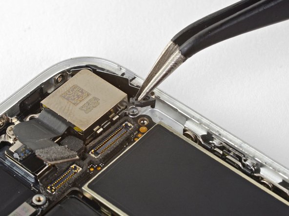
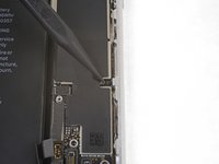
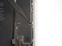
Use tweezers to gently bend the logic board grounding bracket out of the way.
-
-
-
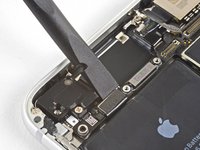
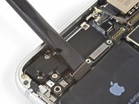
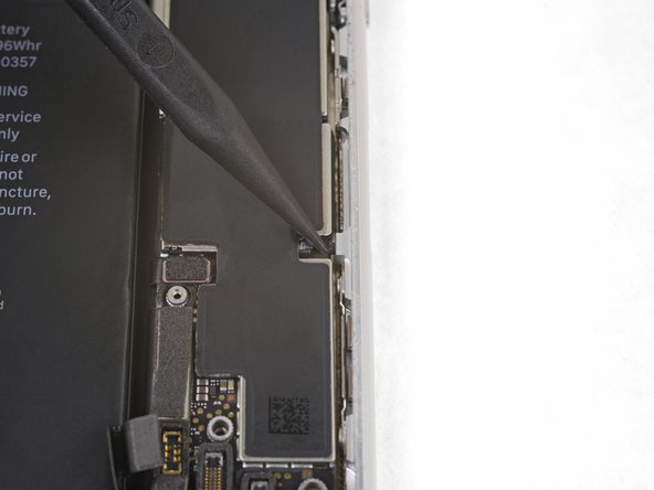
Use the point of a spudger to move the SIM card eject plunger out of the logic board's way.
-
To reassemble your device, follow the above steps in reverse order.
Take your e-waste to an R2 or e-Stewards certified recycler.
Repair didn’t go as planned? Check out our Answers community for troubleshooting help.


