Введение
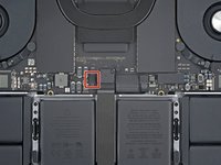
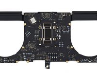
Use this guide to replace the heat sink in your MacBook Pro 16" 2021.
Replacing the heat sink requires you to remove the entire logic board.
For your safety, discharge the battery below 25% before disassembling your MacBook. This reduces the risk of fire if the battery is accidentally damaged during the repair. If your battery is swollen, take appropriate precautions.
You will need replacement thermal paste to complete this repair.
Выберете то, что вам нужно
-
Инструмент, используемый на этом этапе:Magnetic Project Mat$19.95
-
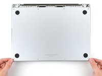
Use a P5 Pentalobe driver to remove eight screws securing the lower case:
-
Four 9.1 mm screws
-
Four 5 mm screws
-
-
-
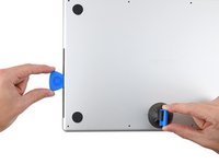
Press a suction handle into place near the front edge of the lower case, between the screw holes.
-
Pull up on the suction handle to create a small gap under the lower case.
-
-
-
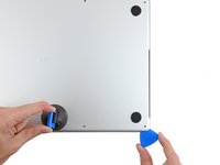
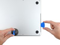
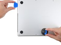
Insert an opening pick into the gap you just created.
-
Slide the opening pick around the nearest corner and then halfway up the side of the MacBook Pro.
-
-
-
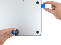
Repeat the previous step on the other side, using an opening pick to to release the second clip.
-
-
-
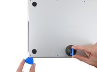
Pull firmly to slide the lower case towards the front edge of the MacBook (away from the hinge area) to separate the last of the clips securing the lower case.
-
Pull first at one corner, then the other.
-
-
-
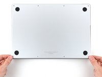
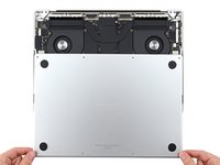
Remove the lower case.
-
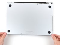
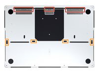
Set it in place and align the sliding clips near the display hinge. Press down and slide the cover toward the hinge. It should stop sliding as the clips engage.
-
When the sliding clips are fully engaged and the lower case looks correctly aligned, press down firmly on the lower case to engage the four hidden clips underneath. You should feel and hear them snap into place.
-
-
-
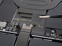
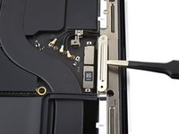
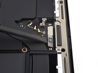
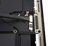
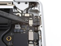
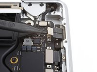
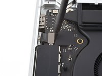
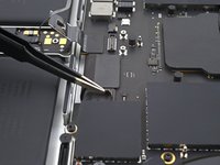
Peel back any tape covering the battery board data cable connector on the logic board.
-
-
-
Use a spudger to gently pry up the locking flap on the ZIF connector for the battery board data cable.
-
-
-
Disconnect the battery board data cable by sliding it out from its socket on the logic board.
-
-
-
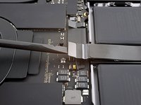
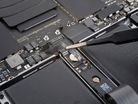
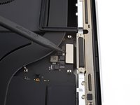
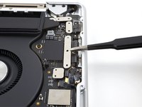
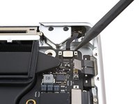
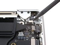
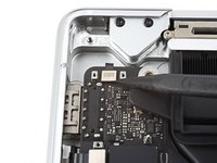
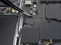
Use a T3 Torx driver to remove the two 2.1 mm‑long screws securing the trackpad cable bracket to the logic board.
-
-
Инструмент, используемый на этом этапе:Tweezers$4.99
-
Use tweezers, or your fingers, to remove the trackpad cable bracket.
-
-
-
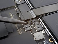
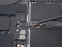
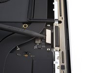
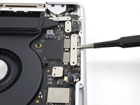
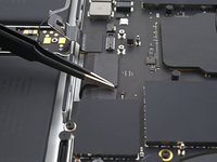
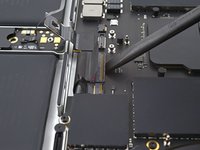
Use the flat end of a spudger to pry up and disconnect the trackpad cable's press connector from the logic board.
-
-
-
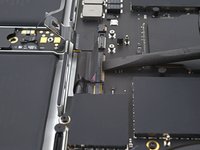
Peel the trackpad cable away from the device, making sure to separate the adhesive.
-
-
-
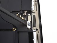
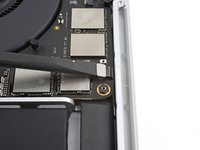
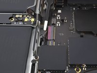
Peel back any tape covering the battery board data cable connector under the large pancake screw.
-
-
-
Use a spudger to gently pry up the locking flap on the ZIF connector for the battery board data cable.
-
-
-
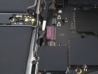
Disconnect the battery board data cable by sliding it out from its socket on the battery board.
-
-
-
Slide blunt nose tweezers under areas with adhesive to separate the cable from the device.
-
Remove the battery board data cable.
-
-
-
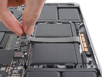
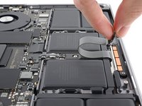
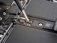
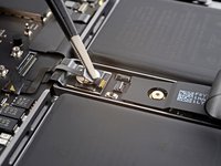
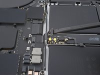
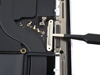
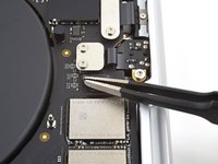
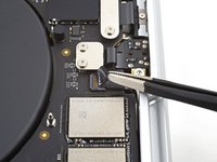
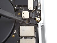
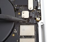
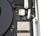
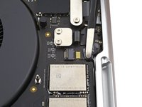
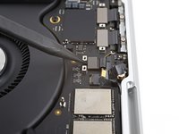
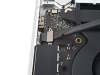
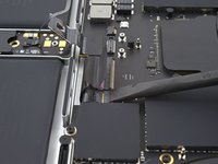
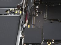
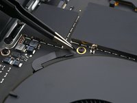
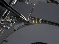
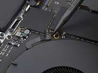
Use a T5 Torx driver to remove the 3.9 mm pancake screw securing the battery power connector.
-
-
-
Use a spudger to lift the battery power connector, disconnecting the battery.
-
-
-
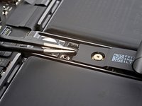
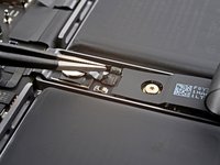
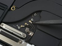
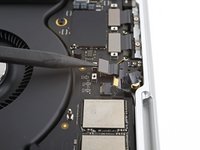
Шаг 20 Unfasten the antenna bar's connector bracket
Внимание: шаги 20-54 взяты из руководства, помеченного как незавершенное.
-
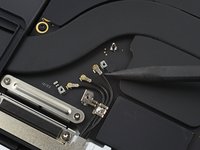
Use a T3 Torx screwdriver to remove the three 2.1 mm screws securing the antenna board bracket and coaxial cable cover to the frame.
-
-
Инструмент, используемый на этом этапе:Tweezers$4.99
-
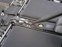
Use tweezers, or your fingers, to remove the cover on top of the antenna bar's coaxial cables.
-
-
-
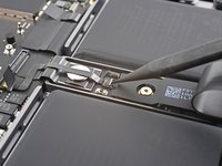
Use the tip of a spudger to pry up and disconnect the antenna bar's coaxial cable.
-
Repeat for the two other cables.
-
-
-
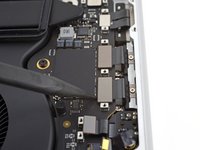
Use a T3 Torx driver to remove the four 2.1 mm screws securing the display cable covers.
-
-
-
Use tweezers, or your fingers, to remove the two display cable covers from the logic board.
-
-
-
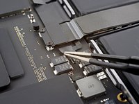
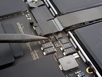
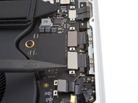
Use the flat end of a spudger to pry up and disconnect the two right-most display cable press connectors secured to the logic board.
-
-
-
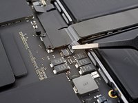
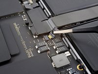
Use a spudger to gently pry up the locking flap on the ZIF connector for the microphone cable.
-
-
-
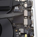
Disconnect the microphone cable by sliding it out from its socket on the logic board.
-
-
-
Use a T3 Torx driver to remove the 11 screws securing the right cable covers to the frame:
-
Nine 2.1 mm screws
-
One 2 mm screw
-
One 3.5 mm screw
-
-
-
Use tweezers, or your fingers, to remove the five right cable covers.
-
-
-
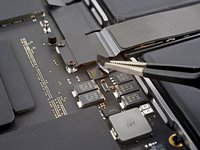
Use the flat end of a spudger to pry up and disconnect the right speaker's press connector.
-
-
-
Use a spudger to pry up and disconnect the headphone jack's press connector.
-
-
-
Use a spudger to pry up and disconnect the right USB-C ports' two press connectors.
-
-
-
Use a spudger to pry up and disconnect the MagSafe port's press connector.
-
-
-
Use a spudger to pry up and disconnect the lid angle sensor's press connector.
-
-
-
Use a T3 Torx driver to remove the six screws securing the left cable covers to the frame:
-
Four 2.1 mm screws
-
One 2 mm screw
-
One 3.6 mm screw
-
-
-
Use tweezers, or your fingers, to remove the three left cable covers.
-
-
-
Use the flat end of a spudger to pry up and disconnect the left speaker's press connector.
-
-
-
Use a spudger to pry up and disconnect the left USB-C port's press connector.
-
-
-
Use a spudger to pry up and disconnect the Touch ID sensor's press connector.
-
-
-
Peel back any tape covering the keyboard and keyboard backlight cable connectors.
-
-
-
Use a spudger to gently pry up the locking flap on the two ZIF connectors for the keyboard cables.
-
-
-
Disconnect the keyboard and keyboard backlight cables by sliding them out from their sockets on the logic board.
-
-
-
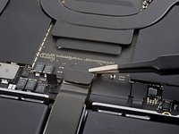
Use a spudger to gently pry up the locking flap on the ZIF connector for the right fan cable.
-
-
-
Disconnect the right fan cable by sliding it out from its socket on the logic board.
-
-
-
Pull the fan cable away from the logic board with tweezers to separate the adhesive.
-
-
-
Repeat the previous disconnection and reposition procedure for the left fan cable.
-
-
-
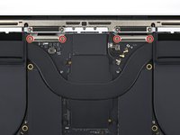
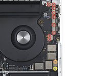
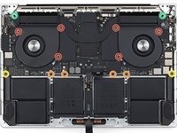
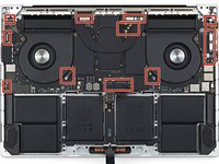
Use a T5 Torx driver to remove the ten screws securing the logic board to the frame:
-
Six 3.8 mm screws
-
Four 4.6 mm screws
-
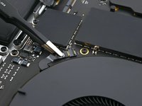
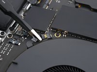
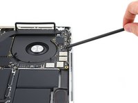
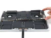
Use a 4 mm Hex driver to remove the two 6 mm screws securing the logic board to the frame.
-
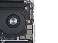
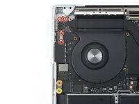
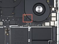
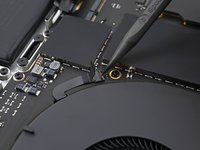
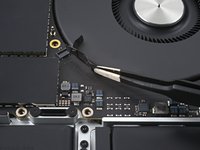
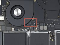
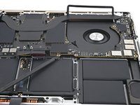
Use a T6 Torx driver to remove the two 6 mm screws securing the heat sink to the logic board and frame.
-
-
-
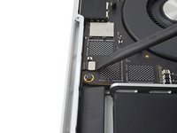
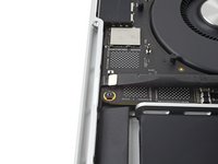
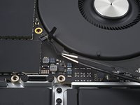
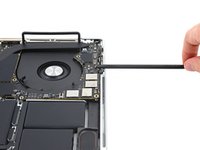
Insert a spudger between the right side of the logic board and the frame.
-
Pry up with the spudger to release the logic board from its clips.
-
-
-
Insert a spudger between the bottom of the logic board and the frame.
-
Pry up with the spudger to release the logic board from its clips.
-
-
-
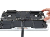
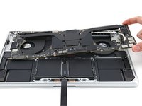
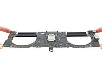
Gently lift up the logic board by its right side to completely release the clips.
-
Pull the logic board away from the left side of the device to separate the HDMI and SDXC ports from their slots in the frame.
-
Remove the logic board.
-
-
-
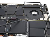
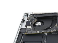
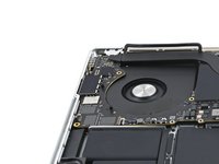
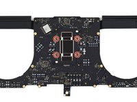
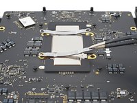
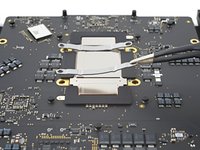
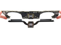
Use a T5 Torx driver to remove the four 3.9 mm screws securing the heat sink to the logic board.
-
-
Инструмент, используемый на этом этапе:Tweezers$4.99
-
Use tweezers, or your fingers, to remove the heat sink brackets.
-
-
-
Use your fingers to lift the logic board up and off of the heat sink.
-
Remove the heat sink.
-


To reassemble your device, follow these instructions in reverse order.
Compare your new replacement part to the original part—you may need to transfer remaining components or remove adhesive backings from the new part before you install it.
Repair didn’t go as planned? Try some basic troubleshooting, or ask our MacBook Pro 16" 2021 Answers community for help.
Отменить: Я не выполнил это руководство.
Еще один человек закончил это руководство.


1Комментарий к руководству
I respectfully disagree with the difficulty rating of “moderate”. Having to remove the motherboard in any Mac is never a moderate procedure. Perhaps for someone familiar with all those tiny connectors, it’s not overly difficult. But for anyone who hasn’t done such an intricate and complicated task, it’s asking for trouble. One tiny mistake, and you’re screwed!
For me, this is yet another reason not to buy a modern MacBook. The older Retina MacBooks require only a few screws and parts to be removed in order to change the thermal paste. The procedure shown here reminds me of the much older MacBook designs. The ones requiring almost total disassembly for the simple task of replacing thermal paste.
By requiring such a complicated procedure, Apple is virtually guaranteeing a limited lifespan. Your average person would never consider such a complicated task, and I’m certain Apple (and others) charge hundreds of dollars for what should be a simple procedure. This is a textbook example of “planned obsolescence”. 🤬