Введение
Use this guide to replace a faulty logic board in your iPhone 5s.
It's important to note that each iPhone's logic board and Touch ID fingerprint sensor are paired at the factory, so replacing the logic board will disable Touch ID unless you also install a replacement home button that has been properly paired to your new logic board.
Выберете то, что вам нужно
Видеообзор
-
-
-
Power off your iPhone before beginning disassembly.
-
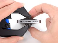
Remove the two 3.9 mm Pentalobe screws from either side of Lightning connector.
 Спросите у FixBot
-
-
-
If your display glass is cracked, keep further breakage contained and prevent bodily harm during your repair by taping the glass.
-
Lay overlapping strips of clear packing tape over the iPhone's display until the whole face is covered.
-
-
-
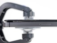
Regardless of the tool you use, you need to be sure you pull up the entire display.
-
If the glass begins to separate from the plastic, as shown in the first image, slide a plastic opening tool between the plastic frame and the metal phone body to pry the metal clips out of the case.
-
-
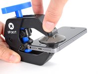
Инструмент, используемый на этом этапе:Clampy - Anti-Clamp$24.95
-
Pull the blue handle backwards to unlock the Anti-Clamp's arms.
-
Slide the arms over either the left or right edge of your iPhone.
-
Position the suction cups near the bottom edge of the iPhone just above the home button—one on the front, and one on the back.
-
Squeeze the cups together to apply suction to the desired area.
-
-
-
Pull the blue handle forwards to lock the arms.
-
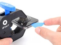
Turn the handle clockwise 360 degrees or until the cups start to stretch.
-
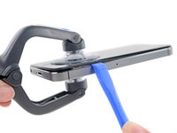
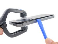
Insert an opening pick under the screen when the Anti-Clamp creates a large enough gap.
-
Skip the next two steps.
-
-
-
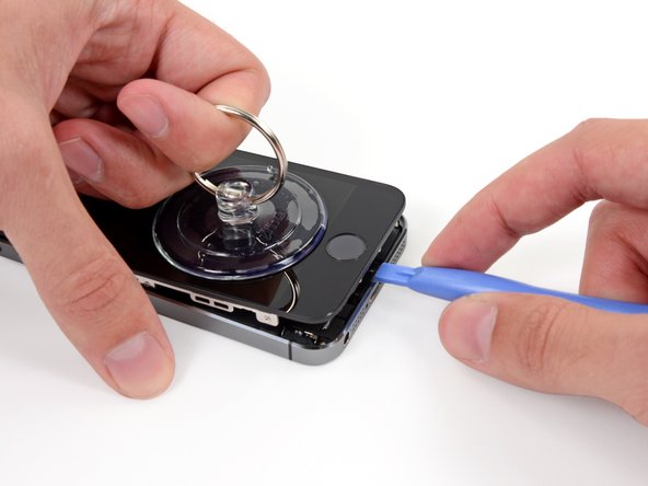
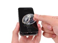
If you don't have an Anti-Clamp, use a single suction cup to lift the front panel:
-
Press a suction cup onto the screen, just above the home button.
-
-
-
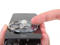
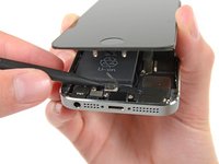
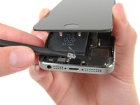
While holding the iPhone down with one hand, pull up on the suction cup to slightly separate the home button end of the front panel from the rear case.
-
With a plastic opening tool, gently pry the edges of the rear case down, away from the front panel assembly, while you pull up with the suction cup.
-
-
-
Pull the plastic nub to release the vacuum seal on the suction cup.
-
Remove the suction cup from the screen.
-
-
Инструмент, используемый на этом этапе:Tweezers$4.99
-
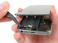
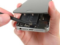
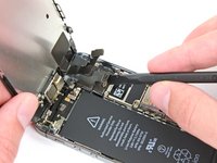
Open the phone just enough to reveal the metal bracket covering the home button cable.
-
Only the phone's original home button assembly will be capable of using the Touch ID functionality. If you rip the cable, installing a new home button will only restore ordinary home button functions, not the Touch ID features.
-
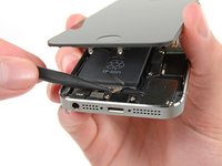
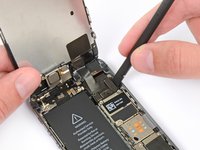
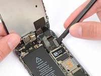
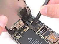
Use the tip of a spudger to push the bracket free and remove it with tweezers.
-
-
-
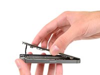
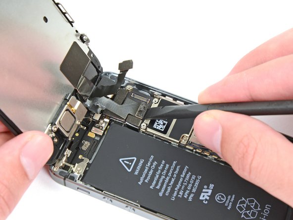
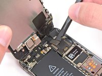
Use the tip of a spudger to pry the home button cable connector up out of its socket.
-
-
-
-
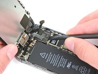
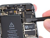
Once the connector has been released, pull the home button end of the assembly away from the rear case, using the top of the phone as a hinge.
-
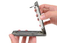
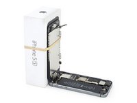
Open the display to about a 90º angle, and lean it against something to keep it propped up while you're working on the phone.
-
Add a rubber band to keep the display securely in place while you work. This prevents undue strain on the display cables.
-
-
-
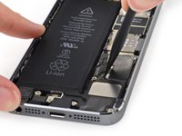
Remove the two 1.6 mm Phillips #000 screws securing the metal battery connector bracket to the logic board.
-
-
-
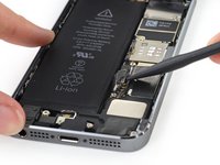
Use the flat end of a spudger to gently pry the battery connector up from its socket on the logic board.
-
-
-
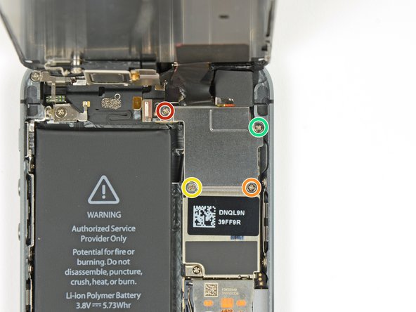
Remove the following screws securing the front panel assembly cable bracket to the logic board:
-
One 1.7 mm Phillips #000 screw
-
One 1.2 mm Phillips #000 screw
-
One 1.3 mm Phillips #000 screw
-
One more 1.7 mm Phillips #000 screw
-
-
-
Remove the front panel assembly cable bracket from the logic board.
-
-
-
Use a spudger or a fingernail to disconnect the front-facing camera and sensor cable.
-
-
-
-
-
Insert a SIM card eject tool or a paperclip into the small hole in the SIM card tray.
-
Press to eject the tray. This may require a significant amount of force.
-
-
-
-
-
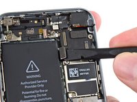
Use a spudger to gently pry the button assembly cable up from its socket on the logic board.
-
-
-
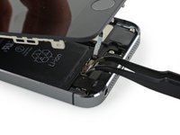
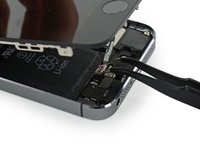
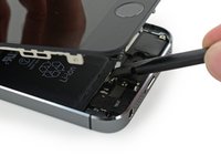
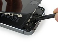
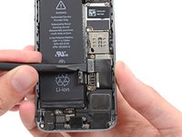
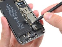
Use a spudger to pry the Lightning connector cable up from its socket on the logic board.
-
Fold the Lightning connector cable out of the way of the logic board.
-
-
-
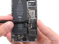
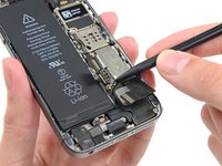
Use the tip of a spudger to pry the antenna cable up from its socket on the logic board.
-
-
-
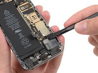
Use the flat end of a spudger to disconnect the rear-facing camera cable from its socket on the logic board.
-
-
Инструмент, используемый на этом этапе:Standoff Screwdriver for iPhones$5.49
-
Remove the following screws from the logic board:
-
One 2.4 mm Phillips #000 screw
-
Two 2.3 mm Phillips #000 screws
-
Three 2.8 mm standoff screws
-
One 2.9 mm non-magnetic standoff screw
-
-
-
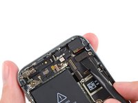
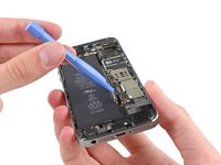
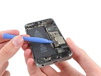
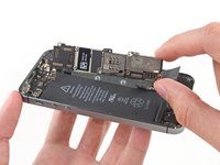
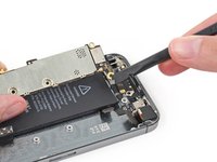
Use a plastic opening tool to lift the logic board up enough to grab with your fingers.
-
-
-
Pull the logic board slightly away from the rear facing camera.
-
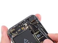
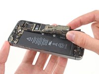
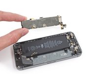
Flip the logic board toward the battery, as if you are turning the page in a book.
-
-
-
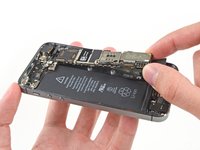
Use the flat end of a spudger to disconnect the antenna cable on the back of the logic board.
-
Remove the logic board from the iPhone.
-
-
Инструмент, используемый на этом этапе:Tweezers$4.99
-
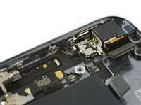
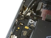
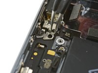
At this point, a small metal plate near the rear facing camera is loose and may come free from its recess.
-
Use tweezers to remove the plate from beneath the bracket to the left of the rear-facing camera.
-
-


To reassemble your device, follow these instructions in reverse order.
Отменить: Я не выполнил это руководство.
338 человек успешно провели ремонт по этому руководству.


38 Комментарии к руководству
Where do I buy the logic board replacement? I didn't see it on the website...
I have the same question, where do I get a replacement board? I am a little wary of ebay from china.
Also what is involved in getting all the small metal bits onto a new "bare" board? Since that is the only way I am able to find a logic board.
You can’t buy the logic boards from iFixit (unless second hand), instead you will have to replaceit with another from a matching iPhone model and install it into your phone.
Check aliexpress.com
Hi I would like to know one small iron plate with hole where it will be placed, I cannot fix it, I do not remember where I oppend it ? can you help me please ?