Введение
If the microphone in your Logitech G733 Wireless Headset is no longer working and you suspect the microphone jack needs to be replaced, you can replace it with this guide. Since getting to the microphone jack requires taking off the circuit board, you can also access many other components with these same steps. For this guide, you will need a Phillips #000 screwdriver, a Torx T4 screwdriver, and soldering equipment. This is a difficult replacement. Soldering experience is advised.
Выберете то, что вам нужно
-
-
Gently pull the left ear pad off, starting from the top.
-
Slide your finger around the edges until it releases completely.
-
Remove the ear pad.
 Спросите у FixBot
-
-
-
Remove the four screws securing the speaker housing with the T4 Torx screwdriver.
-
-
-
-
Remove the speaker housing with care not to strain the connected cable.
-
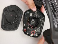
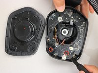
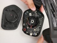
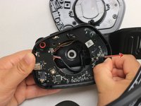
Remove the screw on the bottom right-hand side of the motherboard using the Phillips #00 screwdriver.
-
-
-
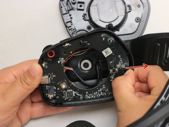
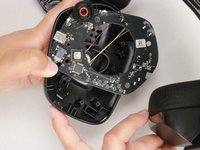
Use your thumb to gently pull back the tab at the upper right-hand corner of the headphone and simultaneously pull the motherboard out.
-
-
-
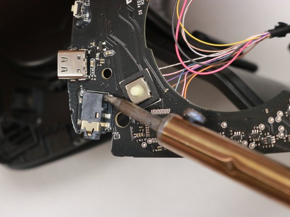
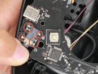
Identify the headphone jack and unsolder all six pins. Using the soldering iron, apply heat to three pins on one side and wiggle the jack free from the melted pool of solder. Repeat for the opposite side.
-
Use the soldering iron again to solder the new microphone jack back to in its spot.
-


To reassemble your device, follow these instructions in reverse order.

Команда

Western Carolina University, Team 1-5, Virtue Spring 2023 Участник Western Carolina University, Team 1-5, Virtue Spring 2023
WCU-VIRTUE-S23S1G5
4 членов
Автор 13 руководств
1 Комментарий к руководству
What is the model of the jack socket